Graphics Window
Navigation: User Guide ➔ Windows ➔ Graphics Window
| Application Window | Message Window | Graphics Window | Access Window | Explorer Window | Trend Window | Controls Window | TagList Window | Project Window |
|---|
Latest SysCAD Version: 13 May 2026 - SysCAD Build 139.37082
Related Links: Graphics, Graphics Commands, ETip: Graphics Window Drawing Grids
Introduction
A SysCAD project is built using Graphics Windows. A project may contain any number of Graphics Windows and each Graphics Window can represent a process flow diagram, and is saved with the extension scg.
The user may navigate around the Graphics windows using the Explorer Window. This window lists all of the Graphics windows in a project in alphabetical order. Therefore, it is a good idea to name the graphics windows in such a way that the start of the process is displayed first, with the other flowsheets in logical order. For example:
- 01 Crushing and Screening
- 02 Milling and Cycloning
- 03 Leaching
- 04 Counter Current Washing Circuit, etc.
In addition, user may group Graphics Windows together in Areas. This allows the user to easily activate and deactivate areas of the project and in the Explorer Window the user may expand and collapse the areas, making it easier to navigate around large projects that have many flowsheets.
Flowsheets are built either by drawing with the SysCAD drawing tool or imported from a DXF drawing. When drawing with the SysCAD drawing tool, the unit operations are inserted into the Graphics Window using the Insert Unit command. Links are used to join the units together via the Insert Link command. When a unit or link is inserted, the unit's mathematical model is added to the solver network, and a graphical representation of the unit is inserted on the Graphics Window. See Graphics Commands for the various drawing commands.
When importing from a DXF drawing, the unit operations are constructed using the Construct Unit and Construct Link commands. When a unit / link is constructed, the unit's mathematical model is attached to some selected graphics from the DXF drawing.
The unit model's mathematical model and its graphics are linked by a tag name:
- A tag name cannot contain spaces and other illegal characters - the tag naming convention options can be found at Project Settings - Graphics and Tags.
- You can locate the unit on a Graphics Window using the Find Tag command. The Access Window for the selected unit can also be opened.
- You can change the tag name at anytime, (see Change Tag).
Open a New Graphics Window
To open a new Graphics window, use one of the following commands:
- If the 'Graphics' menu is active (click on any Graphics window), click on Graphics - New Graphics Window.
- Right click on 'Graphics' in the Explorer Window (if this is not already open, click on View - Explorer) and select 'New Graphics Window'.
- With a project open, use one of the following commands:
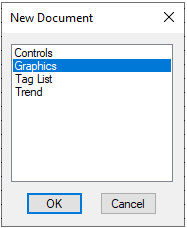
- Window - New Document
- Icon:

- Short Cut Key: Ctrl+N
- Select the 'Graphics' option, and press 'OK'.
Each of these methods will open a new Graphics Window 'xx_Flowsheet.scg.'
Notes:
- This command is only available if a SysCAD project is open.
- This command is not available if SysCAD is solving or running.
- When the project is saved, the Graphics windows will be saved to the \DocsGraphics folder.

Close Graphics Window
To close a graphics window the user must use the Graphics menu. Please see Delete/Close Active Graphic in SysCAD.
Note: Closing a graphics window is normally equivalent to deleting it from the project.
Graphics Window Size
The user may change the size of the Graphics window at any stage by positioning the mouse pointer over the corner, or any edge, of the Graphics window, when the pointer changes to a double-headed white arrow (see diagram below). The user then holds down the left mouse button and may drag the corner, or edge, to increase or decrease the window size.

We do NOT recommend maximising the Graphics Window, as if you do this, it is not easy to move between windows. When the window is not maximised, you may move between Graphics windows, the Access window, Trend windows, etc., by simply clicking on the required window.
In the diagram above, the user may access any unit and the Access window will be displayed next to the graphics window. To access another unit, the user merely right clicks on the desired unit.
If the Graphics window was maximised, the user would right click on a unit and the access window of that unit would also be maximised and therefore to get back to the Graphics window the user would have to click on the 'Cancel' button.
Graphics Grids
- The Graphics Drawing Grids can be displayed on the Graphics Window. User can select:
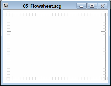
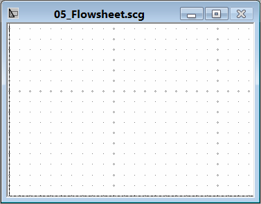
Lines (Default) Ruler Dots 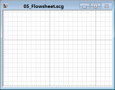


- The Grid Size and display options can be set in the Tools - General Option - Graphics Tab

- User can select when the grid is displayed, see General Options - Graphics
- User can manually toggle the Grid display on/off by pressing Ctrl+G when on the Graphics Window.
- User can define the Big Grid Size. This is the size of each grid, in millimeters.
- The Major Grid is 10x10 of Big Grids.
- The small Grid is for Insert links and moving objects. They are not show on the Grid display.
- The big Grid Count is displayed on the Graphics Window Status bar, it updates with the mouse pointer position.
- When the drawing area is zoomed out sufficiently, only the Major Grid lines are shown.
- A maximum of 200x200 Big Grid elements are shown. If your drawing covers more than this, then you can change the Big Grid value.
- The default Big Grid value is 5mm which allows a grid display over a 1m x 1m area (so fully covering an A1 sheet - 841 x 594 mm).
Graphics Window Background Colours
- The available Graphics Window Background Colour are:
- Black
- Grey
- Light Grey
- Off White
- White
- User can make the colour scheme selection via:
- Menu Command: Graphics | Colour Scheme OR
- Explore Window: Right Click on the Graphics(x) (First Entry) and select Colour Scheme OR
- Menu Command: Tools | General Options | Colours Tab | Scheme
- The background colour selection is global and user based, once the selection is made, it will apply to all projects.
Graphics Symbols Displaying Colours
Please see General Options Colours
Mouse Click on Graphics Symbols
See General Options Mouse for more information.
Pop-up Access Menu on Graphics Window
If you right click on the Graphics Window Background, the nearest unit to the click will turn magenta, and various options will appear in a pop up Access Menu, as shown below. The options available will depend on the nearest unit type (in the example below this is a Pump). This list will also be present if you right click on a unit while pressing the Control key.

|
|


Unit Pop-up Access Window
If you hold down the Shift key and left click (Shift + Left click) on a unit in the Graphics Window, and various options will appear in a pop up Unit Access Menu, as shown below. The options available will depend on the Solver mode and the unit type - in the example below this ProBal and a tank.

|
|
Associated Graphics

|
This dialog box allows the user to show or hide direct links graphics.
The options are available are:
|