ETip: Graphics Window Drawing Grids
Jump to navigation
Jump to search
Navigation: User Guide ➔ Frequently Asked Questions ➔ Tips & Tricks ➔ Graphics Window Drawing Grids
Related Links: Graphics Grids, Insert Graphics, Move, Redraw Link, Graphics Options
Introduction
Drawing Grids provide guide-lines for placement of graphical objects and text strings. It makes lining up of graphical objects easy during flowsheet development.
Why
The new Drawing Grids feature allows you to align and space graphical objects on a flowsheet by providing guide-lines to assist when inserting or moving units, links, symbols or text.
How
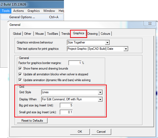
Use the default Grid Display, or change it to your preference in Graphics Options:
- You can change the Grid Display Type: Lines, Ruler or Dots;
- You can set up the Grid size; and
- You can also change when to Display the Grids. The default is set to Display Grid with Editing commands (such as Insert Unit/Link and Move)
Did you know
- When the Graphic Window is the active window, pressing Ctrl+G will Toggle the Grid on/off.
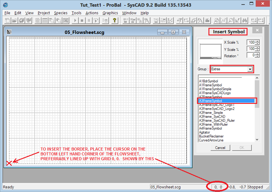
- Grid Count is displayed on the Status Bar, the Grid position is the current mouse pointer position.
- Adding a Drawing Frame at Grid Count 0,0 will assist with defining the "Paper" Size.
Example
The image below shows the path and settings for the drawing grids:
- This example shows the grid display when Insert Symbol command is used:

