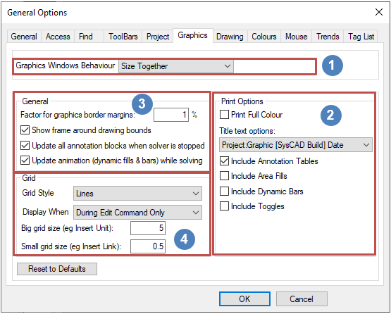
General Options Graphics
Jump to navigation
Jump to search
Navigation: User Guide ➔ Menu Commands ➔ Tools ➔ General Options ➔ Graphics
| General | Access | Find | Toolbars | Project | Graphics | Drawing | Colours | Mouse | Trends | TagList |
|---|
Graphics
| Group | Option | Description | |
Graphics Window Behaviour |
Separate | All Graphics windows are handled separately. | |
| Size Together | All Graphics windows will be sized together. | ||
| Move Together | When a Graphics window is being moved, all Graphics windows will be moved. | ||
| Move and Size Together | When a Graphics window is size or moved, all Graphics windows will be affected. | ||
| Treat as one | SysCAD will display only ONE Graphics window at a time. The user may use the Explorer Window to cycle through the different Graphics pages. In Build 139 and later, user can also use the | ||
Print Options Used by Print Multiple PDF |
Print in Colour Available from Build 139.33457. |
If this option is selected, the printed flowsheets will include the flowsheet status colours. | |
| Title Text Options | The user can select from a list of pre-defined text when printing the Graphics page. Options include 'No Text' or a combination of the following:
| ||
| Animation Print Options Available from Build 139.33457. |
Options to include animation display as single static picture in printed flowsheets, these include:
| ||
General |
Factor for graphics border margins | This factor sets the width of the borders on the graphics windows. The border is the space between the edge of the graphics window and the extents of the drawing. The extents are the furthermost left, right, top and bottom part of any graphics (excluding text such as tags) on the page. | |
| Show frame around drawing bounds | This will display a dashed rectangle around the extents of the drawing in each graphic window. | ||
| Update all annotation blocks when solver is stopped | Updates all Annotation blocks when solve / run is stopped. | ||
| Update animation (dynamic fills and bars) while solving | Updates all dynamic fill displays while solving or running the simulation. | ||
Grid |
Grid Style | Lines | The Drawing Grids will be displayed as solid light grey lines. See Graphics Grids for illustration. |
| Ruler | Rulers will Drawing Grid markings will appear on the four edges of the Graphics Page. See Graphics Grids for illustration. | ||
| Dots | The Drawing Grids will be displayed as light grey Dots. See Graphics Grids for illustration. | ||
| Display When | Never | The Drawing Grid display will be disabled. | |
| Manual | User can manually toggle Grid lines on/off by pressing Ctrl+G. | ||
| During Edit Command Only | Grids will be displayed when edit commands are in use, such as Insert or Move; Grids display will cease when the Edit command is finished. | ||
| On with Edit Command, Off with Run | Grids will be displayed when Edit command is used; Grids display will remain on until Action - Run command is used. | ||
| On with Stop, Off with Run | Grids will be displayed when the project is not Running; Grids display will cease during Project Run only, when the project is stopped, the Grids will be display again. | ||
| Big grid size (e.g. insert Unit) | The size for the large grid. This grid size is used when inserting unit operation. | ||
| Small grid size (e.g. insert Link) | The size for the small grid. This grid size is used when inserting link or moving objects. | ||
| Reset to Default | Pressing this button will reset all Options on the current tab to default settings. | ||
