Insert Graphics Commands
Navigation: User Guide ➔ Menu Commands ➔ Graphic ➔ Insert
| Insert | Edit | Delete | Copy & Paste | Display | Animation | Symbol Management | Construct |
|---|
Latest SysCAD Version: 13 May 2026 - SysCAD Build 139.37082
Related Links: ETip: Graphics Window Drawing Grids, Graphics for Insert Link and Redraw Link
Introduction
This is a subset of the graphics commands which are used to draw and manage SysCAD flowsheets. Note that SysCAD must be in the Edit mode (stopped) for most of these commands to be accessed.
Insert Unit
| Command Button | |
| Command Path | Graphic - Insert - Unit |
| Short Cut Key | Ctrl+U |
This will open the Insert Unit dialog box and is used to build a SysCAD flowsheet.

- Select the required unit model from the list on the left hand side of the dialog box.
- Select the required graphics symbol from the list on the right hand side of the dialog box.
- To insert the unit, left click once on the appropriate position in the Graphics Window with the left mouse button.
- The selected unit will be drawn on the Graphics Window.
- The mouse cursor will be displayed as the name of the model type being inserted onto the graphics page.
- If the unit position is not correct, user can "fine tune" the position by either:
- holding Ctrl + Shift and left click again to alter its position on the flowsheet.
- User can move the newly inserted unit using the arrow keys.
- While the Insert Unit dialog box is open, user can repeat the above steps to insert more unit operations.
- The user may click on the Undo button to undo the last command (insert unit or fine tune position).
- Click the OK button once all required units have been inserted to add them to the flowsheet.
- You can remove all units inserted in an Insert session by selecting the Cancel button, or hitting the Esc button on the keyboard.
Notes:
- You can also watch a short video at Introductory Tutorial - Insert Units into a Flowsheet, which describes how to insert units to build a flowsheet from the Introductory Tutorial.
- The Left Hand list contains all unit model types available for use in the project.
- To display all unit model types available in the dlls which are loaded, enable the Show All option.
- If the Include All Unit Models option has been enabled in the cfg file (refer to Model Selection), then all the unit model types are already displayed and this option will be greyed out.
- This list will default to last unit selected, or to a Feeder/Cross Page connector in a new project.
- The default graphics symbol of the selected unit will be displayed on the top left hand corner to clearly display the currently selected model type.
- The Right Hand list shows a list of the available graphic bitmaps for the chosen unit type.
- To access a FULL list of the graphic bitmaps choose *All* in the Group drop down list.
- Users may save their own graphic symbols to the appropriate folder in \SysCADxxx\BaseFilesUser\Symbols folder. See Graphics Database.
- Changing the unit's rotation or scale can modify the appearance of the unit. These options may be changed before the unit is inserted, or the user may change these later using the Scale/Rotate functionality.
- HINT: To mirror a graphics symbol along the x-axis or y-axis, type in a negative number in the relevant Scale box.
- The unit model's tag name is shown in the Tag field. The user may enter the required tag name when inserting the unit or they may change it at a later stage.
- The Hide Tag check box will show or hide the tag name when drawn on the Graphics Window. The Tag Annotation function can be used to display or hide the tag name after the unit is drawn.
- If the unit needs to be positioned precisely on the Graphics Window, when inserting the unit hold down the left mouse button and cross-hairs will appear to help you position the unit's graphics symbol.
- The coordinates of the cross-hairs are displayed in the bottom right hand corner of status bar and are updated as you move the cross-hairs.
- Release the mouse button to insert the unit.
- You can insert more than one unit at a time by not clicking the OK button after each insert:
- Insert the first unit and then select another unit from the list and insert it.
- If the same unit type is required, you may position each unit by clicking its position on the drawing, without re-selecting the unit type.
- Only click on the OK button when all units are inserted.
- The model type for a unit can be changed once it has been inserted - see Change Unit.
- The Graphics Symbol can also be changed after the unit has been inserted - see menu command Change Symbol.
Insert Link
| Command Button | |
| Command Path | Graphic - Insert - Link |
| Short Cut Key | Ctrl+L |
This command is required to connect two unit operations together with a pipe or link model. The link is constructed by choosing the Source and Destination units, and then the lines are drawn on the Graphics Window to visually display the pipe model. To insert a link, do the following:
- Select the Insert Link command.
- Click on the Source unit for the link. Note that the cursor will change to the Source pointer,
 , when the cursor is in the Graphics Window.
- If the unit selected contains two or more connection ports a pop up box listing all the connection ports for the unit will be displayed, as shown in this example:
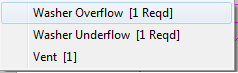
- You must choose a connection port IF a pop up box appears.
- If the unit selected contains two or more connection ports a pop up box listing all the connection ports for the unit will be displayed, as shown in this example:
- The cursor will then change to the Destination pointer,
 . Click on the second unit operation.
- Choose the correct connection port, if required.
- The Insert Link dialog box will appear:
- The user may then accept the automatic link drawn by SysCAD, by clicking on the 'OK' or 'Next' button.
- The Options that govern the appearance of the automatic line drawn by SysCAD are discussed at Default Graphics for Insert Link.
- If the user wishes to draw their own link, then simply click with the mouse button on the first point of the link.
- The automatic line will be deleted and the user may continue to draw the line, as described at Graphics for Insert Link and Redraw Link.


Notes:
- You can also watch a short video at Introductory Tutorial - Insert Links, which describes how to connect units with links.
- Available connection ports for units are shown in black and unavailable connection ports are grey.
- The number enclosed in [ ] refers to the number of connections available for that port.
- A link can be redrawn later using the Redraw Link function.
- Change the Default Link Graphics Options method to 'None' if you do NOT want SysCAD to automatically draw a line. See Default Graphics for Insert Link.
- If you have selected the orthogonal line option, SysCAD will draw only horizontal or vertical straight lines.
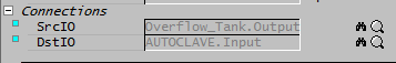
- To check the connections of any link, right click on the link and check the Connections fields on the first page:
 .
.
- You can click on the binoculars or magnifying glass next to the tag to find or access the Source (SrcIO) or Destination (DstIO) unit.

Insert Text
| Command Button | |
| Command Path | Graphic - Insert - Text |
| Short Cut Key | Ctrl+I |
This command will open the Text dialog box.

|
To insert new text:
|
NOTES:
- If no text is entered in the New Text field, the word Text will be inserted.
- This dialog box is used for the Change Text function. To edit an existing Text string, press Select Next, then change the Text, Scale, Rotation or Width and press Apply.
- If the "Show frame around drawing bounds" option is selected on General Options Graphics tab:
- When placing the text, try to avoid placing it too close to the right hand margin, otherwise it will push the "frame" out leaving a large gap at the right hand margin.
- Try using a smaller scale or break the line by creating two separate text strings.
- If using a Width <1, then the text may appear to be to the left of the border, but the "frame" is sized based on width=1.
- Non-standard fonts will use the font shape file (*.shp) for numbers and character mapping. The font files are located in SysCAD139\BaseFiles\Fonts folder. These files differ from the fonts that windows uses to support multiple keyboard/language options.
- Example text added with Standard Font and Cyrillic font is shown below:
- Example text added with Standard Font and Cyrillic font is shown below:

Insert Symbol
| Command Button | |
| Command Path | Graphic - Insert - Symbol |
This command can be used to insert a graphical symbol which has no mathematical model behind it, i.e. "dumb" graphics (see Manipulating Graphics for information). One possible use of this is to insert a border onto a flowsheet.
The command opens the Insert Symbol dialog box:
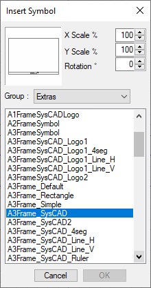
- Choose the graphics group. For a list of all symbols, choose *All*.
- Choose the graphical symbol from the list.
- Insert the symbol onto the flowsheet with a SINGLE LEFT mouse click.
- If the unit insert position is not correct, user can "fine tune" the position by holding Ctrl + Shift and left click to alter its position on the flowsheet.
- If the symbol insert position is not correct, user can "fine tune" the position by either:
- holding Ctrl + Shift and left click again to alter its position on the flowsheet.
- User can move the newly inserted symbol using the arrow keys.
- While the Insert Symbol dialog box is open, user can repeat the above steps to insert more symbols
- You can remove all symbols inserted by selecting the Cancel button, or hitting the Esc button on the keyboard.
- Once all the graphic symbols have been inserted press OK.

Insert Group
| Command Button | |
| Command Path | Graphic - Insert - Group |
This command inserts a group of SysCAD models which has been saved using the Create Group command.
After a group of models has been saved in a text file, it can be inserted into any projects that have access to the text file.
To insert a group, click on the graphics window and then select the Insert Group command. The mouse pointer changes to the word 'PASTE' and the user will see the Insert Group dialog box shown below:

The user should select the group to be inserted from the list of available groups shown in the dialog box.
The user should make any required changes in the dialog box and then click on the insertion point. Options in the dialog box are the same as for the Paste command.
After the insertion point is selected, the user may move the copied selection using the arrow keys.
The 'OK' button will remain greyed out until the user has clicked at least once on the graphics to paste the selection. However, the user may 'Cancel' the Insert Group command before pasting anything.