Graphics for Insert Link and Redraw Link
Navigation: User Guide ➔ Menu Commands ➔ Graphics ➔ Graphics for Insert Link and Redraw Link
Related Links: Insert Link, Redraw Link, Graphics Grids
Introduction
There are 2 occasions when a user may manually draw a link in SysCAD:
- When a user connects 2 units with an Insert Link command and does NOT want to use the default graphics line drawn by SysCAD; and
- When the user selects the Redraw Link command.
The link options will be discussed below.
Video Link
- These 2 videos in the Tutorial section: Insert Links to connect Units in a Flowsheet and Insert Links - Review show the process of inserting a link into a project.
- Please also see the video Redraw Link for a short demonstration of redrawing the links and using the 'Control' and 'Shift' keys to adjust links.
Expanded Redraw and Insert Link Dialog Boxes
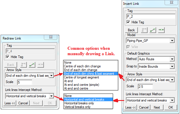
- Tag - the link tag will be displayed.
- The user may change the Tag when inserting a Link, but not with Redraw.
- The user may change the tag at any later stage using the Change Tag Button in the Access Window.
- Hide Tag - The user may show or hide the tag by clicking in this box, or at any later stage using the Show or Hide Tag command.
- Back Button - While drawing the segments for the link, the Back button will allow the user to go back one segment at a time to correct any mistakes.
- Orthogonal and Non-Orthogonal Buttons - The user may select either orthogonal and non-orthogonal (free) lines or a combination of the two.
- HINT: you can switch between the options while drawing different segments of the link.
- Line Break Button - This "lifts the pen" for the next selected point and can be used to manually insert a break into a link. HINT: Holding the Ctrl key down while selecting a point achieves the same outcome.
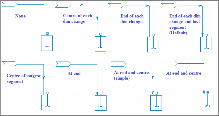
- Arrow Style - The user can choose the positions of the arrows on the link. The default is to insert an arrow at end of each direction change and at end of the last segment. See Link Arrow Options below.
- Scale - The user may change the size of the arrows may increasing or decreasing the scale.
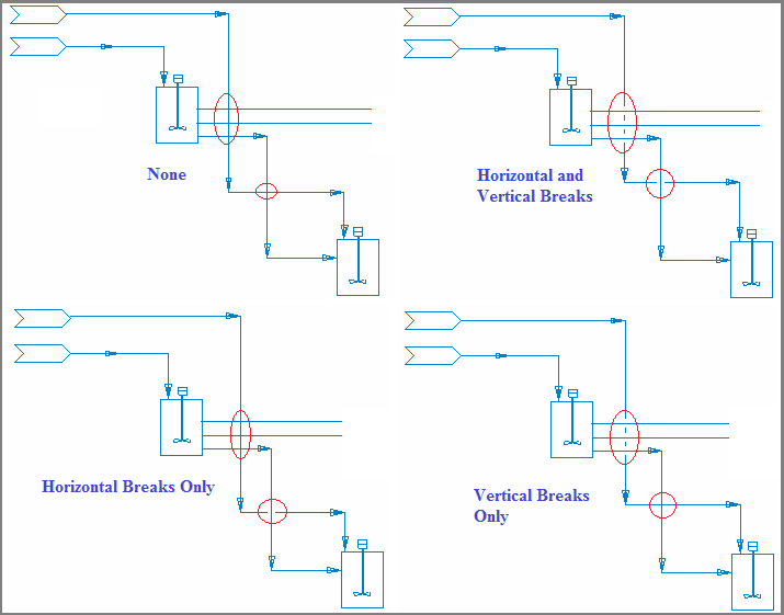
- Link lines Intercept Method - the user may choose if and how breaks are inserted when the inserted link crosses an existing line. See Link Intercept Methods below.
Basic Mechanics for Manually Drawing a Link Graphics
To manually draw, or redraw, an entire link:
- Click the left mouse button once to mark the first point of the line - usually this on the outlet from the source unit.
- If this is during the Insert Link command the automatic line drawn by SysCAD will disappear.
- If this is during the Redraw Link command the existing line will change to secondary high light colour - lime green.
- Click the left mouse button at the point where the line changes direction, if required. Keep repeating this for each required 'elbow' or direction change.
- Click on the final point at the destination unit.
- Click on the 'Next' button to Insert or Redraw the next link, or if no further links are required, click on the 'OK' button.
Notes:
- You can hold the mouse button down to activate the cross-hairs to assist with positioning the link points.
- Use the 'Back' button to undo the previous segment or point.
- If you click on the 'Back' button BEFORE you start manually redrawing the Link, the final segment of the existing link will be deleted. You may continue clicking on the 'Back' button to remove preceding segments of the existing link.
- The graphics link segments can be fine tuned by holding down Ctrl and Shift keys - Moving a link segment or end points.
- Click on the OK or Next buttons to accept the line as drawn, or the Cancel button to cancel the Insert or Redraw link command.
- If the link crosses over existing links, breaks will be added based on the rules of the selected Link Intercept Method.
- If you have selected the orthogonal line option, SysCAD will draw only horizontal or vertical straight lines.
Moving a Link Segment or Link Start or End Points
Control + Shift Keys + Left Click: This combination of keys is very useful for "fine tuning" link graphics. Holding Ctrl and Shift while clicking will have the following results:
- If the user left clicks close to the Start of End point of a link, the point will move to the selected position;
- If the user left clicks close to a segment of a link, that link segment will move to the position selected (i.e. shift segment up/down/left or right).
Adding Lines without Breaks
The user may draw a line without breaks as follows:
- Link Intercept Method = 'None': No automatic line breaks will be added to ANY lines, including links drawn automatically when Inserting Links.
- Shift Key: While drawing the link the user may override line breaks for a segment by holding down the Shift key when clicking on the end point of the segment. The segment that is drawn will contain NO breaks, even if it crosses any other lines.
Adding Manual Breaks in Lines
Users may add manual line breaks as follows:
- Control Key + Left Click: Hold down the Control key and left click will create a break in the link. This may be when it crosses another line, or at any point.
- Break Button: Click on the 'Break' button on the link dialog box and then left click and this will create a break in the link. Again, this may be when it crosses another line, or at any point.
Changing Line Breaks on a Graphics Page
The user may change the line breaks on ALL existing links on a Graphics page. Please see Graphics Commands - Link Breaks. This allows the user to define if existing links have Horizontal, Vertical or NO breaks when they cross other lines.
Link Arrow Options
These options will also change the arrow display for the Default Link graphics,.
Link Intercept Methods
Breaks in link lines are automatically drawn at the intercept of link lines based on the 'Link Intercept Method'. This is only applied to Standard Links (Non-Standard links are ignored).


