Display Graphics Commands
Navigation: User Guide ➔ Menu Commands ➔ Graphics ➔ Display
| Insert | Edit | Delete | Copy & Paste | Display | Animation | Symbol Management | Construct |
|---|
Latest SysCAD Version: 25 February 2025 - SysCAD 9.3 Build 139.37016
Note: These commands only affect the currently selected Graphics window.
Display
Display of Unit or Link Tags
Unit Tags
- Show all Unit tags: This command will display the Tags of ALL units on the selected Graphics flowsheet.
- Hide all Unit tags: This command will hide the Tags of ALL units on the selected Graphics flowsheet.
- Size all Unit tags: This command will change the size of the Tags of ALL units on the selected Graphics flowsheet to the size specified on the Graphics page of General Options (Menu command: Tools - general Options).
Link Tags
- Show all Link tags: This command will display the Tags of all Links on the selected Graphics flowsheet.
- Hide all Link tags: This command will hide the Tags of all Links on the selected Graphics flowsheet.
- Size all Link tags: This command will change the size of the Tags of all Links on the selected Graphics flowsheet to the size specified on the Graphics page of General Options (Menu command: Tools - general Options).
Link Breaks and Arrows
- No Breaks at Link Intercepts: All link breaks where lines cross one another will be removed.
- Horizontal Breaks at Link Intercepts: All Horizontal links will be broken where they cross vertical lines. Any breaks in vertical lines will be removed.
- Vertical Breaks at Link Intercepts: All Vertical links will be broken where they cross horizontal lines. Any breaks in horizontal lines will be removed.
- Apply Arrow style for Links: The default arrow style for links will be applied to all links on the graphics page. Please see General Options - Drawing for more information on where to set the default arrow style.
See also Link Intercept Methods
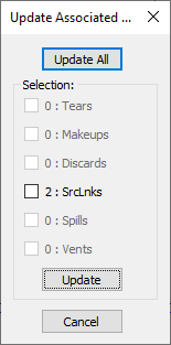
Update Associated Graphics

|
User can choose to update all or selected associated graphics as required. The options include
|
Zoom
Using the Mouse Wheel
Please also see ETip: Flowsheet Navigation using Mouse Control.
The Zoom and Pan mouse wheel action will depend on the settings on the Options - General - Mouse Tab, below are explanations for the default settings only:
Pan:
- The default mouse wheel action is set to Scroll the window vertically, so rolling the mouse wheel will pan the page up/down.
- To pan around the graphics window, hold down the Mouse wheel and drag the graphics in the required direction.
Zoom:
The user may use ![]() + Mouse wheel to zoom in or out the Graphics window.
+ Mouse wheel to zoom in or out the Graphics window.
While the Graphics window is active:
- Hold 'Ctrl' key down and roll the Mouse wheel towards you to Zoom OUT (decrease magnification) at the cursor position.
- Hold 'Ctrl' key down and roll the Mouse wheel away from you to Zoom IN (increase magnification) at the cursor position.
- Roll the Mouse wheel while holding 'Ctrl' and 'Shift' key for Zoom IN /OUT at the window centre (i.e. ignore cursor position).
- Single click on the mouse wheel button while holding 'Ctrl' to zoom back out to view the full graphics page (same as the zoom all command)
NOTES:
- While zoom is active, the mouse cursor changes. You can even zoom in/out and pan with the mouse wheel while busy with some graphics commands such as inserting units.
- To change the Mouse wheel action, please see General Options - Mouse
Using Commands
| Command Button | |
| Command Path | Graphics - Zoom |
| Short Cut Key | Ctrl+M |
This command is used to move around and change the magnification of the active Graphics Window. The zoom command opens a floating toolbar:
- Clicking
 closes the toolbar.
 - The next four buttons allow you to move around the Graphics Window, left, right, up or down respectively. The magnification of the drawing is not changed.
- The next two buttons increase (zoom in) or decrease (zoom out) your view of the drawing.
- The All icon zooms to fit the drawing on the Graphics Window.
- To view a portion of the drawing, with the zoom toolbar opened, drag a selection box on the Graphics Window with the left mouse button. To return to the overall drawing, either click on the All icon, or click once on the Graphics Window.
