Symbol Management Commands
Navigation: User Guide ➔ Menu Commands ➔ Graphics ➔ Symbol Management
| Insert | Edit | Delete | Copy & Paste | Display | Animation | Symbol Management | Construct |
|---|
Latest SysCAD Version: 25 February 2025 - SysCAD 9.3 Build 139.37016
Related Links: Graphics Symbols
Introduction
The Unit Symbol Management commands allow the user to list, change and export graphical symbols used to represent the unit models in SysCAD. This is a subset of the graphics commands which are used to draw and manage SysCAD flowsheets.
Notes:
- SysCAD must be in the Edit mode (stopped) for these commands to be accessed.
- These commands can be used to replace missing unit symbols with standard SysCAD graphical symbols.
List All Unit Symbols
| Command Path | Graphics - Symbol Management - List All Unit Symbols |
| Shortcut Key | Ctrl+J |
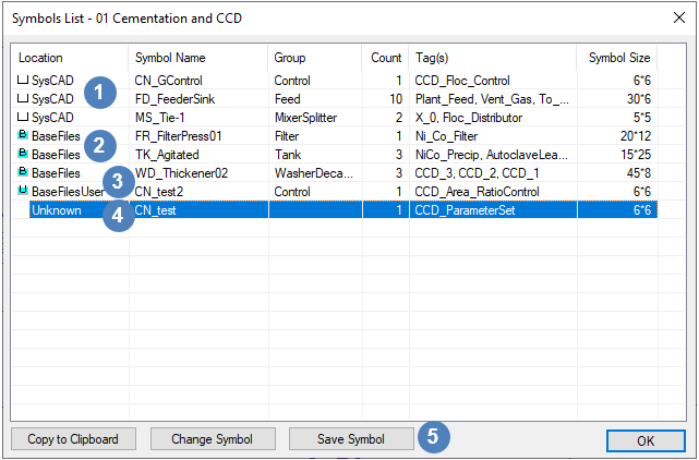
This command will allow the user to view a list of all of the graphical symbols used for the units on a particular flowsheet.
The following dialog box will be displayed:
Columns Headings:
- Location. The location where the unit symbols are saved or stored. The possible locations are:
- Symbol Name. The name of the symbol used for a unit or number of units. The first 2 letters of the name indicate the folder where the symbol is stored as described in Graphics Symbols (e.g. FD - Feed folder, MS - MixerSplitter folder).
- Group. The name of the folder in the Symbol library where the symbol is stored. Group folder corresponds to first 2 letters of the symbol name.
- Count. The number of units with the specific symbol.
- Tag(s). The tags of the units with the specific symbol.
- Symbol Size. The actual size of the symbol definition. Note that this is NOT the scale of the symbol used for tags, but rather the size of the dxf symbol definition.
Data Rows:
 SysCAD: Hard-wired symbols defined in the SysCAD unit models and are typically used as default symbols for units.
 BaseFiles: Dxf symbols defined in the BaseFiles\Symbols folder. These symbols are installed with SysCAD.
 BaseFilesUser: Dxf symbols defined in the BaseFilesUser\Symbols folder.
 Unknown: These are where the symbol definition for the unit model exists only in that specific dxf drawing file. There is no external definition. When using Graphics Copy and Paste, "Unknown" symbols are replaced with default symbols.
- The user may copy the list to the clipboard using the 'Copy to Clipboard' button.
- If the user clicks on a specific line in the dialog box and then clicks on the 'Change Symbol' button this will open the Change Symbol dialog box and the user may then change the graphical symbol for the highlighted unit or all units using the same symbol.
 user can save the unknown symbol using the "Save Symbol" button. See Managing Unknown Symbols for more details.
Notes:
- Please see Graphics Symbols for more information on this subject.
List Unit Symbols
| Command Path | Graphics - Symbol Management - List Unit Symbols |
This command will allow the user to select unit models and view the graphical symbols used for the selected units on a particular flowsheet.
When the user clicks on this command the following menu will be available:
The user may then either:
- Click directly on the required unit; or
- Click on the
 'In Window' option and then draw a window around all of the required units (all units completely inside the window will be selected); or
 - Click on the
 'Crossing Window' option and then draw a window around or crossing all of the required units (all units inside the window or partially within the window will be selected); or
 - Click on 'Units' and ALL of the units on the flowsheet will be selected.
When all required units have been selected click on the ![]() button, or enter.
button, or enter.
The user will then see the same dialog box as displayed in the above section, but with only the selected units displayed.
Highlight Non-Standard Links
| Command Path | Graphics - Symbol Management - Highlight Non-Standard Links |
| Shortcut Key | Ctrl+Alt+J |
This command will highlight all links on a particular flowsheet that are not recognised as standard SysCAD links. The message window will display a count of non-standard links found.
A non-standard link is one that was not created using the normal Insert Link or Redraw Link, it is normally created using the Construct Link command from exploded graphics or imported dxf drawing.
When using Graphics Copy and Paste, "Non-Standard" links are replaced with default links. This can be avoided using the Redraw Link command before copying and pasting graphics.

