Access Window
Navigation: User Guide ➔ Windows ➔ Access Window
| Application Window | Message Window | Graphics Window | Access Window | Explorer Window | Trend Window | Controls Window | TagList Window | Project Window |
|---|
Latest SysCAD Version: 25 February 2025 - SysCAD 9.3 Build 139.37016
Related Links: Quick View, SysCAD Tags, General Options Access
Introduction
The Access Window is a "properties page" used to display information in SysCAD unit models such as configuration data, flow information and connectivity with other units. Access Windows are also used to display global pages such as Plant Model or Solver Settings.
- Information displayed in the Access Window is different for each unit type or global page, and may differ between Steady State (ProBal) and Dynamic solver configuration.
- Two Access Windows are available and may be opened at any time:
- Access.1 is the default Access Window for unit models.
- RIGHT click on a unit's graphics symbol to open its Access Window.
- Access.2 is the default Access Window for global pages. It can also be used as a secondary Access Window for unit models.
- SHIFT + RIGHT click on a unit's graphics symbol to open a second instance of the access window.
- Alternatively, SHIFT + LEFT click on the unit operation, and select the Access.2 "Name" from the pop-up menu.
- For information on how to configure different unit types, see Models help.
- Unit model Access Windows have several common sections including Info, Links and Audit.
Video Link
Please see this YouTube video link for a brief description of some of the Access Window buttons and functionality.
Example
The Access Window for a Feeder/Cross Page Connector is shown below. There may be minor layout differences for different SysCAD versions.
(Please see Feeder-Cross Page Connector for specific information about this unit type.)
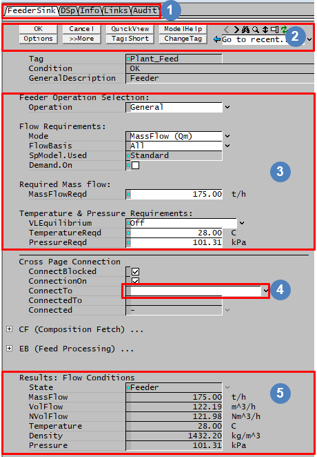 |
Each of these tabs represents a separate page with information about the unit. The first Tab is the Unit Type, in this case Feeder / Sink / Cross Page Connector. | |
| These are access window buttons, they will be explained in detail in Selection Buttons | ||
| These White Fields are INPUT files, the user may change these values. Accessing Data Fields | ||
| Fields with an arrow on the left contain drop-down lists. Click on the arrow to see the available selection. | ||
| These grey fields are CALCULATED fields, the user may NOT change these values. Accessing Data Fields |
Data Entry in SysCAD
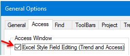
Some Access Window display and behaviour options can be set in Tools - General Options - Access Tab. The various options are described here: General Options Access.
The method by which text or values are entered into Access Window input fields (white fields) depends on the the location of the text cursor, whether or not <INS> (Insert) keyboard option is active, and whether or not Excel Style Field Editing is selected in General Options, as above.
Double-clicking on a text or number input field (i.e. not a droplist or checkbox) enters Text Edit Mode, where standard text editing rules apply. This includes text overwrite (standard behaviour - wide cursor over characters) or insert (keyboard key <INS> has been pressed - thin cursor between characters).
The following applies after a single left-click on the input field:
| For Example: SysCAD Style Editing |
Accessing Data Fields
 The data fields that appear in White are changeable and user inputs are normally required.
- These fields can be number boxes, text boxes (with or without pull down lists), or checkboxes.
- All required fields come with default values.
- The SysCAD Models Documentation offers more help on data fields for individual models.
 The data fields that appear in Grey are NOT changeable by the user. These fields are results calculated by SysCAD.
- Some data fields are only changeable when SysCAD is not solving. That is, when a flowsheet is solving (steady state) or running (dynamic), some originally changeable data fields can be greyed out also.
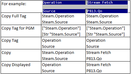
- Most data fields can be copied and pasted into changeable data fields (white cells), trends, MS Excel or Notepad by using the <Ctrl + T> and <Ctrl + V> key strokes. For more information, see section Copy and Paste.
- Most data fields are displayed with a conversion unit - e.g. Mass Flow may be displayed in t/h. The user may change either the Default conversion units, or the conversion units for the individual data field, at any time. Please see Conversions.
- When entering data into SysCAD data fields, the default mode is overwrite. This is represented by a flashing wide text cursor positioned over a character. If the cursor is placed in the white space of a field (to the left of a value, or to the right of text), the new value entered will completely replace the old value. If the cursor is placed on a character/digit, then the normal overwrite rule will apply. Pressing the <INS> key will activate the insert mode. This is represented by a thin text cursor between characters.
- Alternatively, the Excel Editing Style may be used, where the action is to always replace the old value.
- While solving or running, data is not updated on the Access Window, to update, press
 as required. The Access Window data is updated when SysCAD is stopped.
Selection Buttons
| The access window buttons are displayed at the top of every unit Access Window. | |||||||||||||||
| OK Button | This is used to accept all changes made to the Access Window. When a user types in a value, it will be displayed in Blue text with a Blue Dot until the OK button has been clicked. At that point the change is accepted and the value will change to Black.
| ||||||||||||||
| Cancel or Close Buttons | Available from Build 139.37009. The Cancel button is used to cancel all unsaved changes made to the Access Window (i.e., outstanding user-changed values are displayed in Blue). The Close button closes the Access Window. | ||||||||||||||
| Options Button | The options are listed under the Options Button heading. | ||||||||||||||
| Display More or Display Less Buttons | The Once this button has been clicked and all the fields are displayed, the button changes to | ||||||||||||||
| Quick View Button | This will open the Quick View dialog box. | ||||||||||||||
| Tag:Long and Tag:Short Button | This allows the user to toggle variable tags between Long and short.
Examples of differences between Symbols and Tags for a Pipe is shown: |
| |||||||||||||
| Model Help Button | Clicking on this will open the Online SysCAD Help to the section for the unit model associated with the open Access Window.
Note: This will only access the Online Help file if the user has access to the Internet. | ||||||||||||||
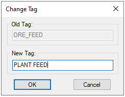
| Change Tag Button | This allows you to change the unit model's tag name from the Access Window.
Old Tag will display the unit's current tag and the user may type in the required tag into New Tag. Please observe SysCAD tag naming rules when specifying the new tag name. Press OK to change the tag. The tag will be changed in the model and any other place where it is referred to within SysCAD, such as PIDs and trend windows. Please also see Change Tag for more information. Notes:
|
| |||||||||||||
| Refresh Access Window Button | When a project is being solved, the access window data is not updated until the solver stops. To force an access window display update manually during a project solve, user can click on this refresh button. User may need to click this repeatedly to keep receiving updated information. Alternatively, the Quick View pop up window or Trend Window can be used to get continuously updated information on selected variables. | ||||||||||||||
| Browsing Graphics buttons |
Pressing For | ||||||||||||||
| Find Unit Button | If the user clicks on this button SysCAD will jump to the Graphics page containing the unit associated with the Access Window and it will highlight the unit. | ||||||||||||||
| Open in Other Access Window Button | Clicking this button will open the other Access Window for the unit (Access.2 from Access.1 and vice versa). User can use the second window to view data on another Tab. The second access window is also useful for comparing data between two different unit operations. NOTE: User can only "see" the second Access Window when NOT using "Maximised Screen". | ||||||||||||||
| Fit Window Vertically Button | Clicking on this will adjust the Access Window height to the full height of the SysCAD window. This is useful when opening a project that was created on a different PC using a different screen resolution. | ||||||||||||||
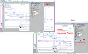
| Move Access.1 beside Graphics Button | Available from Build 139.30447. This button can be used to adjust the layout of the Access window 1 / graphics page(s) to allow both document types be displayed neatly in the application window.
|
||||||||||||||
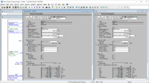
| Move Access.2 beside Access.1 Button | Available from Build 139.30447. This button can be used to adjust the layout of the Access window 2 to allow easy side by side comparison of access window data.
|
||||||||||||||
| Go to previous Access Window Button | Shows the model data for the previous (most recently) accessed unit operation, this is useful for filling in data for controllers. This will also find the unit on the graphics window and brings into view.
For | ||||||||||||||
| Go to recent... Drop Down List | SysCAD keeps a record of the units you have accessed in the past, starting with the most recently accessed unit. You can access any of the listed units by clicking on it. This will also find the unit on the graphics window and brings into view.
For | ||||||||||||||
Options Button
These options are available by pressing 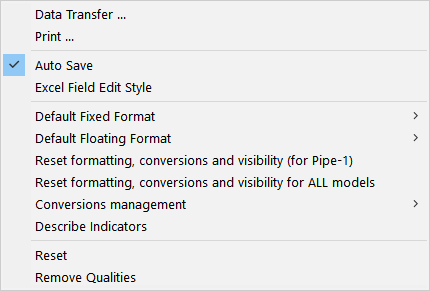 Note: The options shown here are for the latest version of SysCAD. They may differ in earlier versions of SysCAD. |
|
Other Buttons
| |
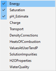 User can select to see more or less groups of data. Please see Additional Properties Options for more information. User can select to see more or less groups of data. Please see Additional Properties Options for more information.
| |
| The Filter On allows the user to filter the species display on the Sp tab. The various Filter Options are described in Species Filter. | |
| Toggles between long / short Species Names. For Example: | |
| Toggles between showing/Hiding the Elemental information. See Hide / Show Elements + Components Button | |
| Toggles between showing/Hiding the Component information. See Hide / Show Elements + Components Button |
Right click on Access Window variables
Right clicking Pop Up Menu for Access Window: 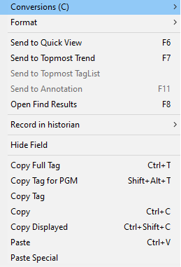 |
Control Tags: See Controlled and Referenced Variables |
Right click on the Access Window Background
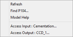
Right clicking on the background of the Access Window, away from the variable names will give you a pop up box similar to this:
 |
|
Left click on the Access Window Background Symbols
For some variables, these symbols: ![]() will be displayed to the right of the field. Clicking on the Binoculars symbol will find the Unit Operation on the Graphics Window, while pressing the Magnifying Glass symbol will open the Access Window for the corresponding Unit Operation.
will be displayed to the right of the field. Clicking on the Binoculars symbol will find the Unit Operation on the Graphics Window, while pressing the Magnifying Glass symbol will open the Access Window for the corresponding Unit Operation.
Access Field Reference Tag Status Colour
A full list of the available status colour can be view by selecting the ![]() Button - Describe Indicators option. When this option is used, the following will be added to the top of the access window, describing the status indicators.
Button - Describe Indicators option. When this option is used, the following will be added to the top of the access window, describing the status indicators.
| Field Indicators:Show Standard | Field Indicators:Show All |
Detailed description of some of the most common status colours are described below:
| Type | Description | SysCAD View |
|---|---|---|
| Stopped | These are variables that can only be changed if SysCAD is stopped (no simulation running). | For example, Tank sub-model selections. If Tools - General Options - Access - Field Indicators:Show All is used, then these fields will be displayed in dark grey colour. 
|
| PreStart | These are variables that will only be executed once during the PreStart Step of the simulation. This means when using these tags in a PGM file, they have to be put inside the Initialise PreStart Subroutine. | For example, PlantModel - Flowsheets See Initialise PreStart Examples for an example of how to set these in the PGM file. |
| Global | Fields with a thin blue Rectangle block indicates the variable is global, changes to this variable will be applied to all access windows. | For example, Pipe - Sp Tab, SpBasis is global |
| Dependent | Fields with Yellow Field Colour means something is setting the value, if the field has no triangle indicator, then it is likely due to Composition Fetch, Feeder Calculator (Bayer, Sugar, Potash) or Solubility. For Example, If composition fetch is set to continuously fetching the composition from another unit, then the composition in the feeder is Linked to the other unit, these fields are presented with the yellow background. User should not change these fields as any changes will be overridden by SysCAD when the project is solved. |

|
| Quick View | Fields with a small turquoise square indicates the variable is displayed in Quick View. | 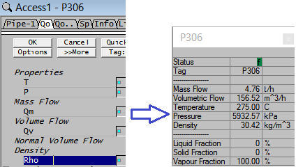
|
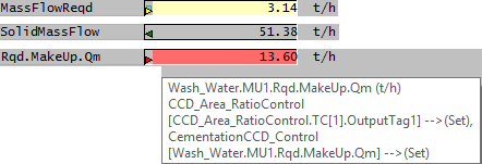
| Set or Get Reference Tags |
NOTE: If the triangle is not shaded (i.e. only the outline is shown) then the tag was not set or read for that particular iteration. |
|
| Manual User Input Value Change | Fields with a Blue Dot indicates the value has been changed by the user, but the change has not been applied yet. To apply the change, hit the |
|
| Inactive Tags | Fields with values displayed in mustard colour indicates the model is NOT active, most likely due to the flowsheet being Deactivated. |
NOTE:The above status colour will also appear on the trend window.
Zero Values Verses Small Number Display
SysCAD displays all data with two decimal points by default. The user can change the number format as needed anywhere on the Access Window, Trend, TagList, etc.
WARNING: There is an exception - by default SysCAD displays zero values as 0 with no decimal points. If a number appears as 0.00, it means the number has a small value and the user may get its exact value by changing the number format. This is not to be confused with true zero values.
Drop List
There are two types of droplist in SysCAD:
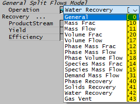
- Returns a value - the drop list that returns a value will have an integer value listed to the right of the droplist, e.g.:
- When making the droplist selection from a PGM file, user needs to set the integer value. For example: ["Cementation.GM.Operation"] = 43
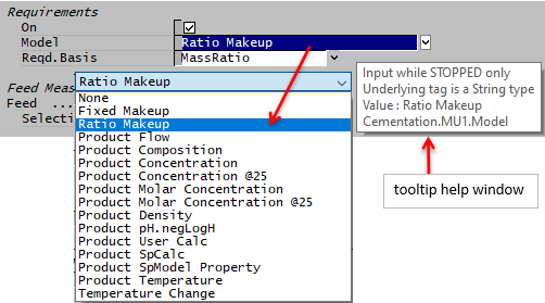
- Returns a string - the drop list that expects a string input will not have an integer value listed.
- In addition, the tooltip window shown when mouse hovers over the drop list field includes 'Underlying tag is a String type' in the description.
- When making the droplist selection from a PGM file, user needs to set a string variable. For example: [Str "Cementation.MU1.Model"] = "Product Composition"
Access Window Short Cut Keys
| Same as pressing the OK button. | |
| Scrolls to the Top Left of the Current Access Window Tab Page | |
| Scrolls to the Bottom Left of the Current Access Window Tab Page | |
| Pans the horizontal scroll bar left/right (1 character width at a time) | |
| Pans the Vertical scrolls bar up/down (1 row at a time) | |
| Highlights the fields which the text cursor travels over (e.g. for Copy/Paste) | |
| Go to the next Access Window tab page | |
| Go to the Previous Access Window tab page. | |
| Displays the model data on the Current Access Window without finding the unit on the Graphics Window. | |
| Displays the model data on the other Access Window, and finds the unit on the Graphics Window. | |
| Displays the model data on the other Access Window without finding the unit on the Graphics Window. |
