Manipulating Graphics
Navigation: User Guide ➔ Graphics ➔ Manipulating Graphics
| Graphics | Graphics Symbols | Manipulating Graphics |
|---|
Latest SysCAD Version: 25 February 2025 - SysCAD 9.3 Build 139.37016
Related Links: Graphics Commands, Graphics Window
Introduction
This section discusses the relationship between Graphical Symbols and Mathematical Models in SysCAD.
When a user inserts or constructs a model (unit or link), they attach a mathematical model to some selected graphics via a unique tag. This is done by creating a graphics dxf "block" (grouped collection of graphical entities) and saving a tag as an attribute for the block. This tag is then used as a lookup to find the corresponding mathematical model.
Therefore, each SysCAD model has two separate components: the Graphics Symbol and the Mathematical Model. Typically you have a 1-to-1 relationship, but you can manipulate SysCAD so that you can have any of the following occurrences:
| Occurance | Illustration | Description |
| Normal | A graphics symbol with an associated mathematical model (normal model graphics) | |
| Dumb Graphic | A graphics symbol with no associated mathematical model | |
| Multiple Graphics | A mathematical model with more than one associated graphics symbol (can be on one or more different graphics pages) | |
| Missing Graphics |
| |
| Missing Model |
|
Terminology used:
| Dumb Graphics | Graphics with no associated model tag or mathematical model. |
| Graphics Symbol | A block of graphics with an associated model tag. |
| Mathematical Model | A SysCAD model with mathematical calculations and algorithms that are evaluated when a SysCAD project is solved. |
| Model Tag | A unique alphanumeric name for each mathematical model. |
Common Commands
| Operation | Illustration | Description |
Insert Unit / Insert Link |
Insert Unit/Link - Used to create a mathematical model and an associated graphics symbol. | |
Change Unit |
Change Unit - Using the existing graphics, replacing the old mathematical model with a new one. | |
Insert Symbol |
Insert Symbol - Used to insert dumb graphics, e.g a drawing border. | |
Change Symbol / Redraw Link |
Change Symbol/Redraw Link - Used to change the graphics symbol of an existing mathematical model. | |
Delete |
Delete - Used to delete both the mathematical model AND the graphics. It can also be used to delete graphical symbols that have no mathematical model or dumb graphics. |
Advanced Commands
| Operation | Illustration | Description |
Construct Unit / Construct Link |
Construct Unit/Construct Link - Used to create a mathematical model and attach it to existing dumb graphics. | |
Explode Model |
Explode - Used to delete the mathematical model but keep the graphics as "dumb" graphics (to return it to just a dxf drawing). | |
Delete Graphics Only |
Delete Graphics Only (1): To delete the graphics but keep the mathematical model (to allow for new graphics to be drawn). | |
| Delete Graphics Only (2): If a model is attached to two or more different Graphics Symbols and you no longer require one of them, you can then use this command to remove the unwanted Graphics Symbol while still leaving the mathematical model attached to the other Graphical Symbol(s). | ||
Explode Symbol |
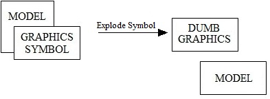
Explode Symbol (1): For a model with associated graphics symbol this will detach the two from each other, but both the mathematical model and graphics symbol will still exist. You must ensure that the mathematical model is subsequently attached to another graphics symbol and you may also use the dumb graphics for another model. | |
| Explode Symbol (2): A mathematical model that is attached to 2 or more graphical symbols and you wish to detach the model from one of the graphical symbols, but keep the mathematical model with the other graphical symbol and the resulting 'dumb' graphics. | ||
| Explode Symbol (3): To 'clean up' a graphics symbol that has an associated Tag, but no mathematical model. | ||
Construct Symbol |
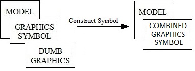
Construct Symbol (1): To attach a Mathematical model that has no associated graphics to some dumb graphics. | |
| Construct Symbol (2): If 'Construct Unit' has been used to create a Mathematical model with an associated graphics symbol, but some dumb graphics was missed. In this case, the user can use 'Construct Symbol' to add the additional dumb graphics to the graphics that already represents the mathematical model. | ||
| Construct Symbol (3): To attach a Mathematical model that already has an associated graphics symbol to some dumb graphics. This allows a single mathematical model to be associated with multiple graphics symbols, for example in an overview drawing. It does allow you to view the same model from two different drawings. However keep in mind that if you delete the mathematical model (by using the Explode or Delete commands), then you will be left with one or more orphan graphic symbols that may need to be deleted or cleaned up separately. Warning: This can become quite messy if not used properly. |
Hints and Comments
1. A user wishes to use the graphics only in a flowsheet from one SysCAD project (A) in another SysCAD project (B). There are 2 ways to do this (the second method is NOT recommended):
- i) Clean up the flowsheet in project A first so that you have 'dumb' graphics to work with project B. Do the following:
- Open the project that contains the required flowsheet, project A.
- Explode ALL of the models, including Links, on the flowsheet using the Explode a Model command. You will now only have 'dumb' graphics on the flowsheet.
- Save the project with a different name.
- Open project B.
- Open a new graphics page
- Use the command Construct Graphics - Load Drawing to import the required flowsheet as a dxf drawing.
- You may now attach mathematical models to the dumb graphics in the imported flowsheet using Construct a Unit/Link.
- ii) Open project B and import the flowsheet as a dxf drawing into a new graphics page using Construct Graphics - Load Drawing, without first exploding all of the models. This can cause the following problems:
- All graphic symbols in the imported flowsheet will still have associated tags. Some of these tags may correspond to existing mathematical models in project B and these models will now have 2 graphical symbols. Some graphical symbols may have tags with no associated mathematical model, i.e. 'orphan' tags. You must clean up these problems before you can use the imported graphics.
- Using the Explode Symbol command, convert all the graphics symbol to 'dumb' graphics by using the
 (In window) or
  (cross window) buttons.
 - When you have Exploded all of the graphical symbols in the imported flowsheet you may then attach mathematical models to the dumb graphics using Construct a Unit/Link.
- i) Clean up the flowsheet in project A first so that you have 'dumb' graphics to work with project B. Do the following:
2. To check if there are any mathematical models with no graphical symbols in a project, go to View-Project, Models tab page. Any models without associated graphical symbols will be shown under the {Missing from drawings} group.
- If the user wishes to remove a model, right click on the model name and choose Delete or choose Delete ALL missing models to remove all models which have no graphical symbols.
- If the user wishes to associate graphics with a model, use the Construct Symbol command to associate dumb graphics with the existing model.
3. To check if there are any graphical symbols with no mathematical models in a project, go to View-Project, Models tab page. Any graphical symbols without an associated mathematical model will be shown under a {Missing from database} group. This is where there is a graphics symbol with a tag but no model can be found for the tag stored in the graphics symbol.
- If the user wishes to remove the graphical symbol, right click on the symbol name and choose Find. Then use the Delete command to remove it.
- If the user wishes to remove the tag stored with the graphical symbol so that the graphics becomes a dumb graphics symbol, right click on the symbol name and choose Find. Then use the Explode Symbol command to remove the tag associated with the symbol.


