Graphics
Navigation: User Guide ➔ Graphics
| Graphics | Graphics Symbols | Manipulating Graphics |
|---|
Latest SysCAD Version: 25 February 2025 - SysCAD 9.3 Build 139.37016
Related Links: Graphics Commands, Graphics Window
Introduction
Graphical symbols are used in SysCAD to represent units on a flowsheet. Lines with arrows are used to represent links or pipes. This gives a visual indication of the connections between units and the type of units. Associated with each symbol or link in the graphics is a Tag which is used to access the configuration and results of the each model, refer to Access Window for more information.
Graphics Windows and Symbols
Graphical symbols to represent units on a flowsheet (including controllers) are inserted onto a Graphics Window. A single project may contain multiple graphics windows. The graphics used on a flowsheet are saved in a single DXF file. The colours of the graphics are used to represent status information of a model and can be customised, refer to Graphics Window for more information.
All graphical symbols available to be inserted into a SysCAD project must be saved in DXF format. Users can insert any symbol from the library of symbols included in the SysCAD installation or they can add their own symbols, refer to Graphics Symbols for more information.
Users can load their own DXF file containing 'dumb' graphics and then associate SysCAD models with these graphics using the Construct Graphics Commands.
Fonts used in the Graphics Page
Upon being loaded or added into SysCAD, all graphical objects, including the frame, default their fonts to “Standard”. This font is an integral part of SysCAD and cannot be modified by users.
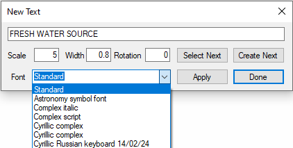
Available from Build 139.34893. For any independent text strings not associated with an object, such as text that is inserted using the Insert Text function, these can be assigned different fonts in the latest build. HOWEVER, the selection of fonts is RESTRICTED to those within the SysCAD139\BaseFiles\FONTS directory, which are different from those available in other CAD packages or from Microsoft Windows.
The text width setting is only applied to independent text strings. It does not apply to text labels associated with graphical objects, such as the TagName of a graphical object.
For users using the Load Drawing feature in SysCAD, please refer to the section on Handling Fonts for information on how fonts are managed in SysCAD.
Graphics Commands
- Graphical symbols can be inserted when SysCAD unit models are created using the Insert Unit command, or just a 'dumb' graphical symbol can be inserted using the Insert Symbol command.
- Once inserted, graphics can be scaled, rotated and moved, refer to Edit Graphics Commands for more information.
- Graphics flowsheets, sections or flowsheets and individual units may be copied and pasted using Copy and Paste Graphics Commands.
- Graphics can be deleted, with or without associated unit models, refer to Delete Graphics Commands for more information.
- Animation graphics that change due to changes in model results can be inserted and updated using the Animation Commands. Animations available include annotation tables, dynamic fills, dynamic bars and toggles.
- SysCAD unit/link models can be associated with 'dumb' graphics using the Construct Graphics Commands.
