FAQ - Graphics related questions
Navigation: User Guide ➔ Frequently Asked Questions ➔ Graphics Questions
| Frequently Asked Questions (FAQ) and Troubleshooting | |||||||||||||
|---|---|---|---|---|---|---|---|---|---|---|---|---|---|
| General Questions | Installation Related | License Related | Project Related | Species Related | Modelling Related | TCE Related | Graphics Related | Access/Trend Related | Reactions Related | Mass & Energy Balance | Flashing / Flash Train | PGM Related | Dynamic Related |
Latest SysCAD Version: 25 February 2025 - SysCAD 9.3 Build 139.37016
Related Links: Getting Started
How do I open a new Flowsheet window?
In an existing project you may use either of the following methods:
- Ensure that the 'Graphics' menu is active (click on any graphics window), click on 'Graphics - New Graphics Window' and this will open a new graphics window.; OR
- Right click on 'Graphics' in the Explorer Window (If this is not already open, click on View - Explorer) and select 'New Graphics Window'; OR
- Click on 'Windows| New Window', and choose Graphics.
Please also see Open a New Graphics Window .
How do I report the graphics window name for a unit?
Using the SysCAD Excel Get Tag Reports, the tag "Graphic" may be used to report the name of the graphics window that the unit is on.
See List Graphics Symbols for examples of how to use this.
How can I change the Background Colour of my Graphics?
The default background scheme colour for SysCAD 9.3 is White.
The user may select a different background scheme colour for all of the graphics in a project, the colour options are Black, Grey (Dark), Light Grey, Off-White and White.
The background colour scheme can be changed:
- From Tools - General Options - Colours
- From View - Explorer, see Explorer_Window - Colour Scheme for more information.
- From Graphics command, Colour Scheme.
Why are Floating Toolbars not visible?
If SysCAD users with differing monitor setups work on the same project, it does sometimes happen that the floating toolbars are not visible to some of the users. This is because when the project is saved the floating toolbar position may be saved according to the monitor setup. The next person working on the project may not be able to see the floating toolbar for the 'Delete', 'Move', 'Scale / Rotate', etc. commands.
Do the following:
- Close the project and using Windows Explorer find the following file in the project:
- Options.Project.ini (previously known as Scd_Prj.ini in older builds)
- Right click on this file and open it using a text editor such as Textpad or Notepad++.
- Find the phrase [GrfDynamicToolbar] and below it there will be values set for XPos and YPos.
- Either set both of these values to 10, or delete them.
- Save the file.
When you re-open the project, you will be able to access the floating toolbars again.
If SysCAD users with differing monitor setups work on the same project, it does sometimes happen that the messages window is placed on the screen with the title bar not visible. User can use menu command Window | Centre on Display to reposition the message window.
How can I hide / display all Tags, Change pipe arrow style or fix line breaks?
On the Graphics Menu - Display, user can:
- Show / Hide all unit Tags
- Show / Hide all pipe Tags
- Set all unit / pipe Tag sizes, the size is set via General Options - Drawing Tab.
- Change all arrow styles
- Fix all line breaks
Please see Display for more information.
Where and how are the Graphics Symbols (used for insert unit) stored?
The distributed graphics symbols are stored in the folder \SysCADxxx\BaseFiles\Symbols. They are grouped into folders of related symbols, each containing .dxf files for each symbol. The dxf file is the actual drawing file SysCAD uses when inserting the unit when using Insert Unit or Change Symbol. For more information on graphics symbols, please see topic - Graphics Symbols.
The Graphics symbols available in SysCAD are listed in this document: SysCADSymbolsList.pdf.
Can I create my own Graphics Symbol (used for insert unit)?
A user can create the new symbol following steps outlined in the topic Creating Symbols from within SysCAD.
- They can save the new symbol using the Menu Command Graphics | Symbol Management | List All Unit Symbols - Save Symbol button. See topic Saving the New Graphics Symbol
- For user with access to a drawing package that can save or export in an AutoCAD dxf format(e.g. AutoCAD, Microstation, Powerdraft and progeCAD), follow this topic Creating Your Own Symbols Using External CAD packagefor hints on how to create a new symbol for use in SysCAD.
How do I 'Stretch' a Graphics Symbol?
- Activate the 'Scale/Rotate' command, either from the Icon,
 , or from the drop-down menu, Graphics - Edit - Scale/Rotate.
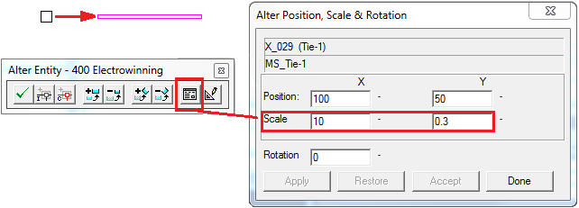
 - Click on the unit that you wish to stretch and then click on the 'Dialog' button in the Scale/Rotate menu.
- Enter the required values in the X and Y boxes (in the example below we have stretched the Tie in the X direction, scale = 10, and squeezed it in the Y direction, scale = 0.3.
- Click on the 'Apply' button and if you are happy with the result, click on Accept or Done.
- If you are not happy with the result, you may go back to the original symbol by clicking on the Restore button, or you may enter new X and Y scales.
The example below shows a Tie that has been stretched in the X plane and squeezed in the Y plane:
How do I add a Vertical or Horizontal dividing line on a Flowsheet?
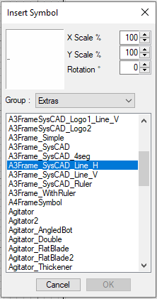
Using the Graphic - Insert - Insert Symbol command, insert one of the line symbols (such as A3Frame_SysCAD_Line_H or A3Frame_SysCAD_Line_V) from the Extras group. Then use the Graphics - Edit - Scale/Rotate command (as shown in the previous topic) to change the X or Y scale to adjust the line to the appropriate length.
How do I create a Mirror image of a Graphics Symbol?
- Activate the 'Scale/Rotate' command, either from the Icon,
 , or from the drop-down menu, Graphics - Edit - Scale/Rotate.
 - Click on the unit for which you wish to create a mirror image, and then click on the 'Dialog' button in the Scale/Rotate menu.
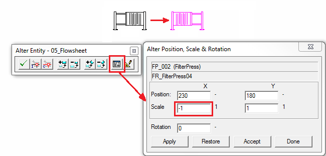
- To create a mirror image in the X plane, enter a negative value in the Scale box for X.
- Similarly, to create a mirror image in the Y plane, enter a negative value in the Scale box for Y.
- Click on the 'Apply' button and if you are happy with the result, click on Accept or Done.
- If you are not happy with the result, you may go back to the original symbol by clicking on the Restore button.
The example below shows a mirror image that has been created in the X plane for a Filter Press.
Can I use a Graphics Symbol other than the default set for the unit operation?
Yes, simply choose a different group of symbols from the Group dropdown list.
Can I have a drawing border for my flowsheet?
A drawing border will always add to the presentation of the flowsheet. The best way to do this is to add the border as symbol. Use the Insert Symbol function and select the Extras drawing group. Typically an A3 frame should be selected, but you can choose A1/A2/A3/A4FrameSymbol, depending on the Size of the flowsheet.
After the border has been inserted it can be rescaled using the Scale/Rotate function and it can be positioned using Move function.
Please also see Introductory Tutorial - Insert a Flowsheet Border, which has a short video describing how to insert a flowsheet border.
NOTE: Available from Build 139.32735., user can select a "border" to be used when a new graphics page is added. Any new graphics page added after this selection has been made will contain the drawing border automatically. This can be configured in:Project Settings - Graphics and Tags tab.
How do I align Graphics Symbols on the Flowsheet
Although there is no align Symbol functions in SysCAD, there are a couple of ways to help with placement of graphics symbols:
- SysCAD has snap to grid option, set via Tools | General Options | Graphics, use an appropriate grid size to help with major unit operation placement. Recommend a large grid size of 6, 10 or 12 for A3 frames. A grid size of 10 is 10mm when printed on A3 (420 x 297 mm).
- Use the grids as a guideline when inserting and moving graphics symbols.
- Once a graphics symbol has been placed, user can use the keyboard arrow keys to make some positioning adjustments.
See Move Graphics Symbols for more information.
Can I add a title to my flowsheet?
The best way to do this is to use the graphics command Insert Text. If a border is required around the text, simply use the insert symbol function to add a box. (Eg: Group: MixerSplitter - TitleBox01, Group: Extras - A3Frame_Simple)
Can I add a table of numbers to my PFD flowsheet?
Technically, yes but it is more common to use Excel for these reports. The function is called Insert Annotation Table. Use Graphic | Animation | Insert Annotation Table to create the table. Use Graphics | Animation | Update Annotation Table to edit the table and Graphics | Animation | Refresh Annotation or Refresh All Annotation to update the numbers during solve as the table is only updated on stop.
Can I copy the graphics page as a bitmap?
This is very easy to do, and there are a number of ways of achieving this:
- RIGHT CLICK on the BACKGROUND of the ACTIVE flowsheet in SysCAD and choose Copy bitmap (it is the last option on the pop up menu). A "Print screen" of the graphics flowsheet window only (see note below) will be copied onto the clipboard.
- With the desired flowsheet currently the ACTIVE window, choose Graphic - Copy & Paste - Copy Bitmap (it is the last command). A "Print screen" of the graphics flowsheet window only (see note below) will be copied onto the clipboard.
- Right Click on the Graphics name in the SysCAD Explorer window and select 'Copy Bitmap to Clipboard' (also see Explorer Window)
NOTE: This will copy what is on the active graphics page as is. Thus if the graphics page is zoomed into an area, it will only copy that particular section. Also, SysCAD puts this bitmap in mono colour i.e. black lines on white background.
You can paste the bitmap into other applications.
The standard "Print Screen" keyboard key can also be used to copy a full screen colour image to the clipboard.
What do I need to do to import an external drawing?
If you have access to a pre-drawn CAD drawing, whether it was created in AutoCAD, Microstation (and so on), as long as you can export the drawing to a DXF format, you can import it into SysCAD. However, there are a few things to keep in mind:
- All blocks on the CAD drawing must be exploded, these include polylines and hatches. In particular, check for blocks that are "Off" and "Locked" - turn on all the layers and deal with any blocks.
- Any external references must be removed; these will often include any frames used. Frames can exist on the drawing, but only if it is part of the drawing, not as a reference drawing.
- After all the blocks are exploded, it is best to do a purge on the drawing to remove any unused layers and styles; this will keep the drawing as small as possible.
- Long text strings and foreign language characters may cause problems
Once you have the DXF drawing ready, create a blank graphics page in SysCAD, use menu option Graphics | Construct | Load Drawing and select the dxf drawing you have created. Check that all the lines and symbol have been imported properly, if not, go back to the other drawing package and fix any unexploded symbols and try again.
Please see How to create a customised drawing frame using external CAD packages for more information.
How can I manipulate the graphical representation of models?
The simplest and most commonly used commands are Change Symbol for units and Redraw Link for pipes. There are a number of ways to change the graphics symbol associated with a mathematical model or a tag. The point to remember is that when you insert or construct a unit or pipe, you have attached a mathematical model behind some selected graphics of your choice. Therefore, there are two separate components: the Graphics Symbol and the Mathematical Model. These two normally have a 1-to-1 relationship, but you can manipulate SysCAD to change either or both of the components.
Please see Manipulating Graphics for a detailed description of the commands and how they manipulate the graphics and the mathematical models.
Orphan Models (Models without Graphics)
If for some reason there are Orphan models in the project and the user is 100% certain they are not required, then user can delete these orphan units using one of the two methods:
- Delete via the Explorer Window
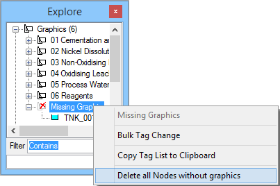
- Select menu command View - Explorer to open the Explore Window, under the graphics tree, there should be a section called Missing Graphics, open that tree to get a list of all the unit operations in the project without graphics.
- If user wish to delete all the orphan models, simply right click on the word Missing Graphics to bring up a popup menu, select the option to Delete all nodes without graphics.
- Once that is done, save the project, close and reopen Explorer to refresh the explorer list. User should find that the missing graphics is fixed.
- Manual Workaround - If for any reason the missing model fails to show up on the above list, you can try the following workaround:
- Using Graphics Insert Symbol, add a dummy symbol to the flowsheet.
- Using Graphics Construct Symbol, type in the name of "orphan model", then select the dummy symbol as the graphics. Press OK to combine the model and symbol.
- The model can now be deleted using Graphics-Delete.
I am missing flowsheets, how can I find and reopen them?
- With the project open: <menu command> Project - Open Containing Folder - Project folder. This will open the MS file explorer showing the SysCAD project files. Go to subfolder "DocsGraphics" to make sure the graphics page exists. If the missing graphic page exists (has been saved with the project), it can be re-opened again.
- With the project open: <menu command> Window - Open Document, browse to the desired graphics page and press "Open" to open the file.
- Repeat steps above to open all the missing flowsheets.
- Save the project.
NOTE: If the missing page has never been saved with the project, then it cannot be recovered.


