FAQ - Modelling related questions
Navigation: User Guide ➔ Frequently Asked Questions ➔ Modelling Questions
| Frequently Asked Questions (FAQ) and Troubleshooting | |||||||||||||
|---|---|---|---|---|---|---|---|---|---|---|---|---|---|
| General Questions | Installation Related | License Related | Project Related | Species Related | Modelling Related | TCE Related | Graphics Related | Access/Trend Related | Reactions Related | Mass & Energy Balance | Flashing / Flash Train | PGM Related | Dynamic Related |
Latest SysCAD Version: 25 February 2025 - SysCAD 9.3 Build 139.37016
Related Links: Getting Started
I have a multi-core or multi-processor machine, will I notice a speed increase during solve and can I control how the machine uses the processors?
The SysCAD application and solver has been designed to take advantage of multiple processors. The SysCAD software has been programmed to create 'worker threads' to divide the workload and take advantage of multiple processors. This capability has been improved, and continues to receive attention, in subsequent SysCAD versions. Different parts of the main application such as graphics, historian queries, trends, etc are processed on different threads. The operating system balances the workload of assigning active threads to different processors.
The most important and beneficial part of multi-processor support is for the main SysCAD solver. For a flowsheet this division is done at the model level and is based on the ability to solve models in parallel given that all inputs are known. Hence if a flowsheet topology is such that after tearing (breaking recycles), a number of parallel paths exist, gains will be achieved. With care, some strategies are available in both Dynamic and Steady State projects to break a flowsheet into independent parts to take advantage of parallel processing.
If on the other hand the flowsheet consists of one long sequence of unit operations there are no benefits in solver for using a multi-processor machine.
There are a significant number of synchronisation points during each iteration, and some actions that do not support parallel processing, that together prevent full utilisation by SysCAD solver of a large number of processors.
The tag '$Solver.SolverThreadsRequired' in View - Solver Settings allows control of Multiprocessors for use by the network solver. The options are:
- Match LogicalProcessors-1 : (Recommended option) SysCAD will use the Threaded Solver and automatically select the number of solver worker threads based on the number of available logical processors -1.
- Match LogicalProcessors : SysCAD will use the Threaded Solver and automatically select the number of solver worker threads based on the number of available logical processors.
- Match Cores : SysCAD will use the Threaded Solver and automatically select the number of solver worker threads based on the number of available CPU Cores.
- Single Threaded : Do NOT use the Threaded Solver. Use a single thread.
- UserSpecified : The user can specify the number solver worker threads.
How do I join the flows between pages?
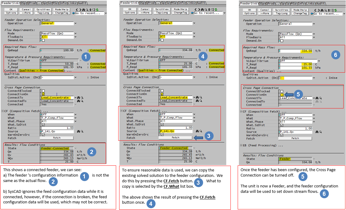
This is done via the Feeder-Cross Page Connector unit operation, in the Cross Page Connection section, which is located on the first tab page of the Feeder unit operation access window. Simply choose the Tag name of the unit operation (must be another Feeder/Cross Page unit op) to be connected to from the dropdown list of the ConnectTo field.
Please see Set up Cross Page Connection for a diagram.
NOTE that you can only have one connection made at any one time. Deselecting the ConnectionOn check box can break connections.
For more information on this, please refer to the Cross Page Connector.
Can I select the graphics pages that I want to run?
You can activate and deactivate graphics pages in one of the following ways:
- The easiest way (and recommended method) is via menu command Graphics - Group Operations. The 'Group Operations' interface allows the user to activate/deactive multiple graphics pages at the same time. For users that have grouped their graphics pages by area, then all graphics pages in an area can be activated/deactivated at the same time.
- Via the Explorer Window, by right clicking on the required Graphics name and clicking on Activate or DeActivate. See Manipulating Graphics Windows.
- Via View - Plant Model - Flowsheets Tab.
NOTE: When running the pages separately, please make sure all feeders to individual pages are configured properly. NOTE also if these feeders were cross page connected prior to being deactivated, users can use the Composition Fetch option in the access page to get the solved flows. See Hints and Comments for more information on Composition Fetch.
Is there a best practice / modelling guideline available?
Please see Modelling Guideline and Project Check List.
How do I add particle size distribution data to a project?
Firstly, you need to add size distribution to your project configuration before you can use it in a project.
Open SysCAD, but do not have a project open, and then go to ‘Edit - Project Configuration’ and choose to ‘Edit’ the project configuration file of interest.
During step 1 of 2 of Edit Configuration, ensure that at least one Size Distribution models are selected in the required model list. Also make sure the "Include All Unit Models for selected Dlls" checkbox is ticked.
Click on the Next>>> button
You will now have a number of tabs to choose from. The first step is to define a new size distribution (Size Distribution tab) including selection of solid species, then define the sizes for the size distribution (Sieve Series tab), then define the desired measurements (Measurements tab) – please refer to Size Configuration.
When you have finished setting the size data in the configuration file, you can close the configuration editor.
How do I add or remove particle size distribution data from a Stream?
Add Size Distribution Data
You must have already added the size distribution information to the project configuration file (see How do I add particle size distribution data to a project?).
With the project open:
- Access the relevant feeder with solids - this is where you will set the size of the solids entering the plant;
- On the first tab of the Feeder, you will should see a heading called 'Qualities' (If you do NOT see the 'Qualities' heading, then you do not have Size distribution enabled in your project);
- If this has a + box on the left side, click on this and it will show the qualities that you can set in this feeder – one of which is ‘SzDist.Action’.
- Click on the arrow next to the SzDist.Action box and select ‘Create’ from the drop down list:
You will now see that you have quite a few extra tabs visible in the feeder, the first one is DSz. Go to the DSz tab and you will see that you can now input the size distributions for the solids that you selected in the configuration file.
After running your project, you will now have size distribution information in all streams with these solids in your project.
Remove Size Distribution Data
There are times when you only need this information at the front end of the project, e.g. for the crushing, screening and milling sections. Thereafter you may not be interested in the size distribution data. You can remove this information in the following way:
- Go to the stream where you would like to remove the size distribution information and click on the Qi tab. If the Qi tab is not visible you may need to untick the Simplify and/or tick the Show.Qi options on the Pipe-1 tab page;
- Go to Qualities and go to ‘SzDist.Action’ and select ‘Remove’ from the drop down list.
- If you have already solved the project and the project contains recycles, you will need to remove the PSD from these recycle streams. To do this, you can simply remove the qualities from the current project solution by right clicking on the "graphics window background" and select "Global Remove Qualities". This will force SysCAD to rebuild the stream quality information for the whole project.
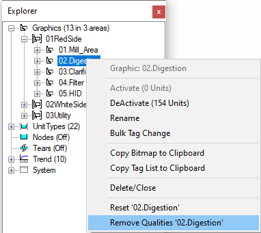
- If you don't want to reset the whole project, you can selectively remove them per graphics page. To do so, from the Explorer Window, right click on a selected Graphics page and select "Remove Qualities 'xxxx page name xxx'", this will clear the "qualities" from the solution for the current page and force stream quality information to rebuild upon solve.
- Solve and check if the PSD data has been removed properly. If PSD data persists, then check to see if there are more than one stream with PSD data that need to be removed.
Please also see Content - Qualities and Material Flow - Qualities.
How can I configure a Tank or Tie with Phase or Species split to pass 'Demand' correctly?
The Operation mode on the Split tab, MUST be set to General for the unit to pass the Demand from the downstream pipes to upstream pipes.
Please see Passing Demand set in Pipes through a Unit for further information.
Note that instead of setting the demand in the pipes, it is possible to set the demand in the tank or tie using the Splitter sub-model.
What is the "W:More than one demand source available" error and how do I troubleshoot this?
For complex flowsheets, we often have a stream being split into multiple streams, then they can be recycled or re-joined to form a single stream. This means the demand source may go through multiple paths to arrive at the same point and thus can have multiple sets of solution if a fixed point is not found.
Please see Demand - Troubleshooting for an example to demonstrate the problem and on how to fix this issue.
How to troubleshoot PID controller
Please see PID Controller - Hints and Comments section for some general information on how to set up the controller and some basic tips on how to tune or troubleshoot the controller.
There are some simple videos available based on the PID controllers used in the tutorial: Video Links
How do I Improve Convergence when using a PID to control Temperature?
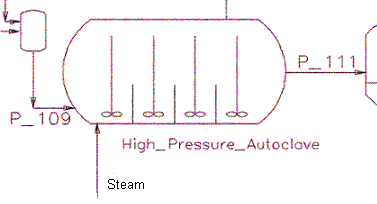
If a project includes a PID controller that is changing some variable to obtain a required temperature, the speed of convergence can be improved by using a EHX block in the measured stream. This is best demonstrated by example:
|
|
How can I set the flow in a closed-loop circuit?
See also: How do I set up a closed loop that can handle user-defined flow variations?
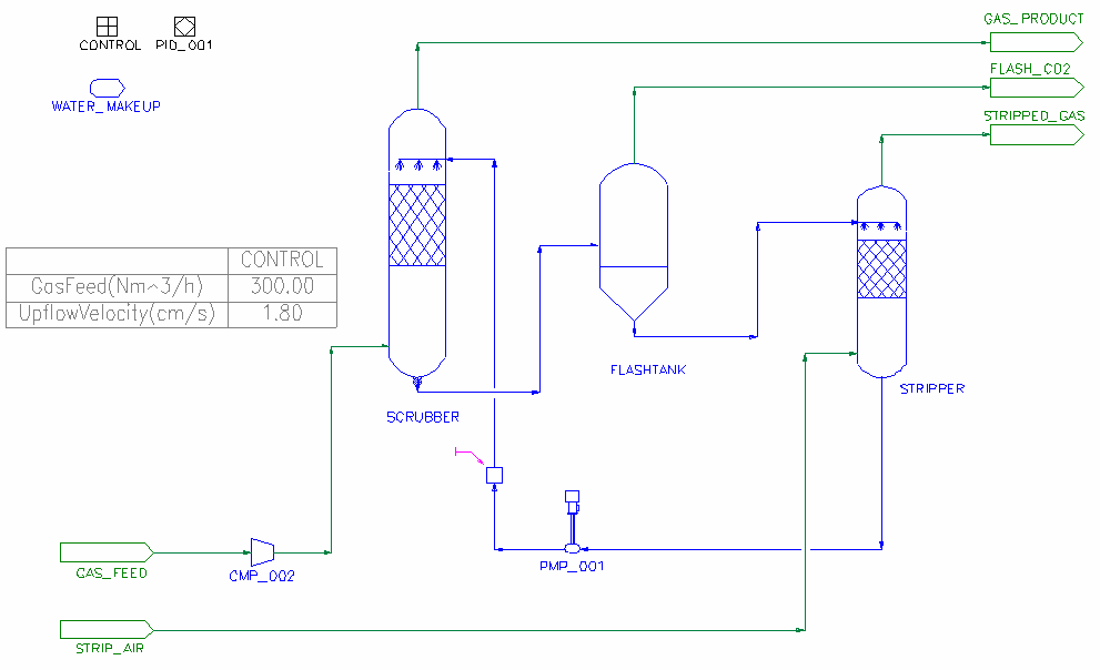
For example, suppose you want to model a gas scrubbing system where a fixed flow circulates in a loop, but with some losses due to entrainment, evaporation and bleed-off.
- For increased flow:
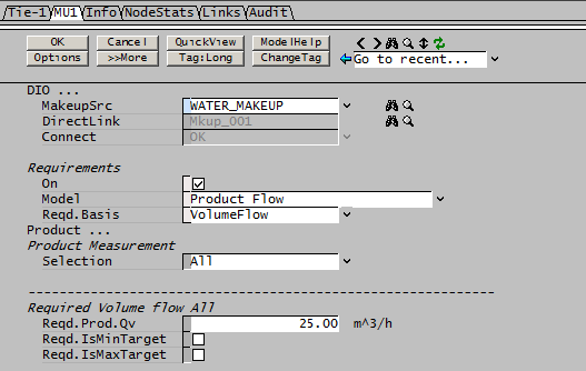
- this is easily handled using a Makeup Source. Add a tie into the loop where you want to set the flow, enable the makeup block and configure it with the required flow:
- The makeup will set the flow to 25m^3/h into the scrubber. Once the flow loop is set up, with the flow recirculating back through the stripper, any losses will be "made up" by the Makeup Block (MU).
- For decreased flow:
- this is easily handled using a Discard Sink. enable the discard block and configure it with the required flow, any extra flow will be discarded by the Discard Block (DB).
How do I set up a closed loop that can handle user-defined flow variations?
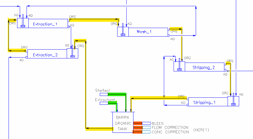
Here we will use the the distributed example Nickel Copper Project - organic circuit for solvent extraction as an example:
- In the above picture, the closed loop is highlighted in yellow.
- To set up the closed loop with increased flow, this includes the initial build up of the re-circulation flow:
- Makeup blocks are added to meet the flow requirements, and extractant concentration (in that order, these are marked in green).
- It is important to note that if more than one makeup block is used, the makeup blocks are evaluated in sequence. So, if the required concentration is high, then the flow added by MU2 will be significant, and may cause the final flow out to be noticeably higher than the requirements set in MU1.
- If this is the case, user can set up a General Controller (PGM file) to re-calculate the flow for MU1 to exclude the amount added by MU2
- User can see this by looking at the "SX Control" in the distributed example Nickel Copper Project:
- ["Barren_Organic_Tank.MU1.Reqd.Prod.Qv (m^3/h)"] = ReqdOrgFlow + CrudLosses - ["P250.Qo.Qv (m^3/h)"]
- When the flowrate has reached its pre-set target, the makeup flow will stop. If organic is lost within the circuit, the makeup will serve as a top up.
- To set up the closed loop with decreased flow, this is in addition to the normal bleed stream, which is typically very small:
- the reduced flow can be set up using 2 discard blocks, one to meet the flow requirements, the other is to correct the concentration (in that order, these are marked in red).
- the flow and concentration setpoints used for the discard blocks are the same as used for the two makeup blocks.
- It is important to note that if more than one discard block is used, the discard blocks are evaluated in sequence. So, if the inlet concentration is too high, then the flow removed by DB2 will be significant, and may cause the final flow out to be noticeably lower than the requirements set in DB1. This should only happen for a single iteration before the makeup restores the flow to its correct value on the next iteration.
Split Flow Configuration in General Model Changes
If the General Model has been enabled in a Tie or Tank and a number of streams have been set to have user defined flows and the user then either adds or deletes one of the outgoing streams from the unit, the configuration of the remaining streams may change. This is because SysCAD orders the streams automatically from the unit, based on the order in which they were constructed. And when a stream is added or deleted, then SysCAD will automatically adjust the stream order.
To avoid this issue, it is Strongly recommended that the user manually sets the Priority of the streams when configuring the General Model. SysCAD will then not automatically change the stream order, but will retain the user defined priorities.
Please see SplitFlow for further information.
How can I add Gland Seal water to a Pump in Steady State Mode?
The Pump 1 model does not allow more than a single input, so this will not allow the user to add Gland Seal water to the Pump. Rather use the Tie model and change the Operating Pressure method to RequiredP. This will allow you to set the required pressure from the 'Pump'
You can then:
- Add a Makeup Block to the Tie with the required Gland Seal water flow; or
- Add another feed to the Tie with the Gland Seal water.
How do I set up Feeder information automatically when running flowsheets separately?
If the project has never been solved before, user must set up the feeder information manually. However, if information is available elsewhere in the project, user can use Data Transfer to copy the information across.
If the project has been solved prior, user will notice that there is intermediate information available in the feeder. In these cases, the user can use the feeder CF.Fetch Self Flows option to copy the intermediate image and use it as feeder configuration.
See Feeder-Cross Page connector - Composition Fetch for more information.
SysCAD is returning an error Insufficient Memory, what does that mean?
SysCAD is a 32bit Application and is therefore limited to 4GB for the program and data. The "Insufficient Memory" error means there is something in the project that is consuming excessive memory.
The tag “PlantModel.Stats.Memory.AvailVirtual (Mb)” in PlantModel - Statistics tab page is useful to track what’s happening.
There are two possible likely causes:
- some bug consuming memory and not freeing it up – you will notice this if over time the Memory.AvailVirtual continues to decline.
- The project is too large and using excessive memory – you will notice this if after a solve, the Memory.AvailVirtual continues to remain relatively constant over time
Please contact support@syscad.net if you encounter this issue. If you could provide some descriptions on how the error occured and some tracking data for the Memory.AvailVirtual value, including: after project load, solve, save, re-load and so on that would be helpful.
Can SysCAD be used to size equipment?
In general, SysCAD does not provide equipment sizing data, although some models provide basic data such as residence time in a Tank, theoretical heat transfer area for a Shell and Tube Heat Exchanger or theoretical aperture for a Screen.
A SysCAD model provides flows, temperatures, compositions and other data that can be used by specialist manufacturing companies to design the equipment, but equipment sizing will usually involve considerations well beyond what a simple flow model can provide.
For example, in sizing a heat exchanger, you need to know exactly how fouling and scaling will affect the performance. If you size the heat exchanger based on “clean” conditions, you may find that after a few weeks (or even days) in service, the performance has dropped off dramatically. Such equipment is then designed with a large safety factor so that it can continue in operation for a long period before being taken out of service for cleaning.
You can use SysCAD to get reasonable estimates of pipe sizes, tank volumes and so on based on simple empirical models (maximum flow velocity for pipes, residence times for tanks, etc.), please refer to MP Example Files for some basic examples.
Ultimately sizing for equipment (and warranties on performance) is performed by the equipment manufacturers. The SysCAD model provides the basic data, and is useful for preliminary sizing, but much more input is usually required.
Can SysCAD be used to provide cost estimates (capital or operating costs)?
SysCAD does not provide estimates of cost (capital or operating).
A SysCAD model provides flows, temperatures, compositions and other data that can be used by specialist manufacturing companies to design the equipment and provide cost estimates.
If you have a simple cost formula, such as reagent cost per tonne, or power cost per kWh, these can be incorporated into the SysCAD model using a General Controller. The unit cost would be an input parameter to the model and the model would use the calculated reagent or power required to determine the total cost which could be reported in Excel. Alternatively, cost models can be developed in Excel which accept results from the SysCAD model as inputs to the cost calculations.
What does error message "Negative Cp. Output Temperature may be incorrect!" mean?
These messages usually appear when you have a stream with aqueous species with small or zero fractions of H₂O(l). The specific heat is a correction to water specific heat based on the mass fraction of the component and may be negative. If the stream is mostly water, there is no issue (since the aqueous species will just reduce the Cp by some small amount), but if there is little or no water present, the correction will take Cp negative.
If the message does not include the unit tag where the error is occurring, it usually indicates that this is only happening in some internal containers, such as when mixing the streams to a unit, in between the execution of sub-models, or the message is generated by SysCAD within an iterative loop. This means that sometimes these error conditions don’t apply at the final state, thus they could be false or misleading error messages and can be ignored.
The location of these units is not easily identified as described above. One possible suggestion would be to run a report to see where in the model the fraction of water may be low.
To avoid this issue, either ensure there is enough water fraction left or precipitate out the solute species when the solvent is low.

