Demand
Navigation: User Guide ➔ Solver ➔ Demand
| Project, Model and Solver Settings | Simulation Modes and Solver Setup | Solver Methodology, Convergence and Tolerance | Solving Models | ||||||||||||
|---|---|---|---|---|---|---|---|---|---|---|---|---|---|---|---|
| Project Settings | Solver Settings | Plant Model | Constants | Simulation Modes | ProBal Setup | Dynamic Setup | Solver Status | Solver Methodology | Convergence Methods | Tolerance Testing | Evaluating Sub-Models | Flash Train | Mass & Energy Balance | Referenced Variables | Demand |
Introduction
Demand functionality is only available in Steady State. Note that for Dynamic models, Transfer Pull achieves a similar functionality.
There are two types of Demand functionality:
- The Flash Train macro model uses Demand to transfer steam flow demands from one unit that generates steam (e.g. a Flash Tank), to another unit that consumes steam (e.g. a Shell and Tube Heat Exchanger, Barometric Condenser). The user does not have to set any variables to make this functionality work. When the user connects and configures the unit models correctly to form a "Flash Train", SysCAD will recognise all the units that form a Flash Train and will automatically calculate operating pressure and pass the steam Demand between the units.
- Users can set up General Demand requirements in Pipes (see Demand in Pipes) which connect back to Feeders which have the Demand functionality enabled, see Flow Requirements in a Feeder. The Demand required is transferred through Pipes and through Ties and Tanks by use of the Split using the demand option.
- Some Unit Models include options to calculate a General Demand which is then fed back through pipes. Therefore, in these cases, it is unnecessary to set the demand in the pipe.
- Users may also set up Demand in the Splitter sub-model, as described below Setting up Demand in the Splitter Sub-Model.
NOTE: The Makeup Block (MU) is often a simpler method to meet requirements.
This section will only discuss user defined General Demand. The demand functionality in the Flash Train macro model generally requires less user intervention.
Setting up a demand stream (Steady State)
Example on setting up a tank input stream as demand stream (in Steady State):

The above example has a tank with three outlet streams, each with a known flowrate. There is also a side stream feed to the tank. The aim is to have the demand stream feed the correct amount to the tank to satisfy all the outlet requirements. When the project is solved, SysCAD will calculate the demand stream and input 13 t/h.
The above will also work for the tie model.
Setting a Feeder to Demand Mode
For the Demand functionality to work, the demand stream must be connected to a Feeder, with the Demand.On enabled, as shown in the figure below:

The user may also set the Maximum and the Minimum flows allowed from the Feeder, as shown above, where the maximum flow allowed is 3600 t/h (default value). If you know their will always be some flow, it is strongly recommended to enter a non-zero value for the minimum. That way some flow always occurs which can help downstream unit models correctly calculate demand required in subsequent iterations because it will have stream properties available for the calculation from the small flow.
Selecting Demand Options in Plant Model
Global Demand options are set on the FlwSolve Tab of the Plant Model.

- User can select to block the Demand in Tear streams (recommended).
- The amount available can be shown by selecting the ShowDemandAvail box. See the next heading for more information.
- The tolerances used when testing whether to display condition warnings when a required demand flow is not being met can be set here.
Setting up Demand in a Pipe
On the outlet streams, the user has to specify the Qm_Demand in the pipes, as shown below:

- The Qm_Avail.Source and Qm_Avail.Dest are only visible if the ShowDemandAvail tick box is selected in the PlantModel - FlwSolve tab page. (See the previous heading.) The Available source will show the maximum amount it has available, normally set by the Demand.Max in the Feeder(s).
- In the pipe shown above, the user has set the Required Demand (Qm_Demand.Reqd) to 5 t/h
- The Source has provided this demand, Qm_Demand.Source = 5 t/h.
- There are no further Demands set downstream, and therefore Qm_Demand.Dest is not valid, i.e. a *.
The user may Block the Demand from perpetuating either up or downstream by selecting the Qm_Demand.Block tick box. This is useful as follows:
- To prevent the Demand from a Feeder from perpetuating downstream to a pipe where it is not required;
- To prevent the Demand from one of the outlet paths of a tank or tie from perpetuating downstream to where it is not required;
- To choose which Feeder the downstream Demand will be met by when there are two possible feeders in Demand mode. Block the one that you do not want to be used;
- To stop Demand in a recycle stream.
If a pipe has its demand blocked, then as well as the stopping the demand from perpetuating upstream, it will also prevent the user from specifying a demand in that pipe.
Setting up Demand in the Splitter Sub-Model
On the Split tab of a Tie or Tank, the user must select Operation = 'Demand Mass Flow', as shown below:

|
Notes:
|
Passing Demand set in Pipes through a Unit
- The Demand value will automatically be passed through Tanks and Ties that do NOT have 'Split Flows' enabled.
- If 'Split flows' IS enabled in a Tank or Tie, then on the GM tab the user MUST set the Operation to 'General' and:
- The split to any pipes that have Demand enabled MUST have QmMode set to (Demand);
- If the user requires a Phase or Species split to another pipe, then they must set the QmMode for that pipe individually.
- Please see the diagram below for an example:
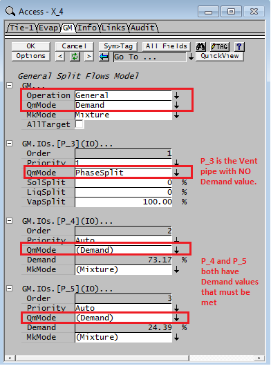

In the Tie shown above:
- Pipes P_4 and P_5 both have Demand values;
- Pipe P_3 is required to take all of the gases from the unit, so the QmMode has been set to 'PhaseSplit' with 100% of the vapours exiting in this stream.
SysCAD will now meet the Demands in pipes P_4 and P_5.
NOTE: Not all unit models support passing of Demand logic through connected pipes.
Understanding Demand Logic
The basic functionality of Demand logic is to take the various downstream demand values and pass these values (with adjustments as necessary for side streams) upstream until a single Demand source is found which then adjusts its flow to meet the total demand requirement.
In a model such as a tie with multiple outlets, it will sum the demands of the outlet pipes that have demands specified and pass this result (with adjustments for any outlet streams that are not in demand mode). If the Tie has multiple inlets it will pass the demand value upstream on the inlet pipe that has a Demand feeder upstream. If more than one inlet pipe has an available Demand feeder, then an error message is given (there are effectively an infinite number of solutions because you could arbitrarily split the required flow between the two paths).
If there is a recycle within your Demand network, then there are potentially an infinite number of solutions because as you increase the flow at the demand feeder you can increase the recycle and still meet the demand requirements. It is recommended that the user Blocks any recycle paths in the demand network. This is usually performed automatically by selecting PlantModel.BlockInTears, as described above. It may be possible to move the location of the recycle Tear by selecting a pipe in the recycle that is not part of the demand path and changing "Tear.ReqdType" to "ManualTear".
Not all unit models support Demand logic. Demand Values can not be calculated and passed correctly through some unit models such as separators with multiple inlets and outlets.
Tracing the demand values through the network
- Pipes: To follow the Demand values upstream and downstream within a Demand network, SysCAD displays the demand values in the pipes. This is in a section with heading "General Demand" on the pipe and shows the demand value passed through that pipe.
- Tie and Tank: When there is Demand logic detected, a Demand summary table is shown which is ideal for viewing all the outlet pipe demand values and the inlet pipes that have a demand source.
- Models specifying demand required: In addition to pipes, some unit models can specify a Demand (e.g. Simple Heat Exchanger, Desuperheater) these will have a display of Demand required, etc. These calculated requirements will override any downstream demands.
- The first value seen (from the source direction) will be treated as an override of any downstream Qm_Demand.Reqd so you would get demand not met messages in downstream pipes/unit operations where the demand value is different.
- Other models: Some unit models such as Desuperheater, also display information of the Demand Values passed through the model, even though that model is not specifying a Demand required value.
Example projects using Demand
The Demand Project is an example project distributed with SysCAD that shows the General Demand functionality used in a project.
Hints and Comments
- When setting a Demand value in pipes or units, the user must ensure that it is connected via the network to a single source of material that has Demand enabled (usually a Feeder), see Flow Requirements in a Feeder. If there is no connection to a feeder with Demand enabled, then the Demand functionality will not operate correctly. It is possible to have other feeders with fixed flows, but there must be ONE feeder in demand mode so that SysCAD can adjust its flowrate to meet the demand requirement.
- If the user sees the warning More than one demand source available then this means that a unit is either connected to 2 or more Feeders with Demand enabled, or a recycle is repeating a Demand. The user must block the demand from one of the Feeders to the unit or in the recycle, as each unit may only have a single Demand source available if it is to work correctly.
- The demand logic often works better if the QmReqd (Min) field in the Demand Feeder is a small number rather than zero. This is because some demand logic in models usually requires at least some flow to calculate the actual demand amount required.
- Demand rarely works in recycles and Tear streams, it is not intended for this purpose. The pipes with Tears are normally configured to block the Demand logic, see Selecting Demand Options in Plant Model. Therefore check that you have no recycles (look for Tear associated graphics symbol) between your required demand value and your demand source. Often the recycle Tear can be moved (by changing Tear.ReqdType to ManualTear) to another pipe in the recycle where the other pipe is not in the demand path.
- A non-zero total demand is required. SysCAD does not support a total demand target of zero.
- If the feed to the unit is non-zero, but all outlets of the unit has 0 demand specified, then the non-zero input will be distributed to all the outlets streams.
- Check that the demand is not being set in multiple pipes in series (i.e. in a path). The first value seen (from the source direction) will be treated as an override of any downstream Qm_Demand.Reqd so you would get demand not met messages in downstream pipe where the demand value is different.
Troubleshooting
More than one demand source available
We will use an example here to describe some of the potential issues user may experience:

In the above example we have
- Once Demand source feeder, it splits three ways (1st level), then some of the flow will join back and feed the tank at the bottom of the page.
- Because we have not told the three way split how to divide its flows, there are potentially "infinite" number of solutions to this problem. In this case, the unit will give the warning "More than one demand source available", and it will show the list of sources in the demand table of the unit. In our case, both P_004 and P_009 can act as the source stream, we need to eliminate one of these to allow SysCAD to proceed with a calculation.
- To do this, we can select stream P_009, and tick the "Qm_Demand.Block" tickbox.
- Now we are left with only one demand source stream and SysCAD will be able to calculate the correct amount of makeup to this unit.

Demand network not formed
As discussed in Understanding Demand Logic, the position of a tear stream within a network can prevent the demand network from forming.
A relevant example is provided in the distributed project "Cooling Tower Example", where the cooling water network includes a tear stream.

In this example, if the system tear is placed at the cooling tower outlet pipe, the demand network will fail to form. As a result, the makeup water flow will not be calculated. To correct this, the tear stream must be relocated to another pipe within the circuit that does not interfere with the demand calculation (as noted in Note 3 of the diagram). Alternatively, the recycle loop can be broken using the Feeder–Sink method, as described in Tear overview.