Flash Train
Navigation: Models ➔ Energy Transfer Models ➔ Flash Train
| Project, Model and Solver Settings | Simulation Modes and Solver Setup | Solver Methodology, Convergence and Tolerance | Solving Models | ||||||||||||
|---|---|---|---|---|---|---|---|---|---|---|---|---|---|---|---|
| Project Settings | Solver Settings | Plant Model | Constants | Simulation Modes | ProBal Setup | Dynamic Setup | Solver Status | Solver Methodology | Convergence Methods | Tolerance Testing | Evaluating Sub-Models | Flash Train | Mass & Energy Balance | Referenced Variables | Demand |
Related Links: Troubleshooting Flash Trains, FAQ - Flash Train related questions, Exporting Steam in a Flash Train
General Description
The Flash Train functionality is only available in Steady State.
The Flash Train is not a unit as such, but rather it consists of a number of units, which together comprise a 'Flash Train'. A Flash Train typically comprises of one or more steam 'sources' connected to a steam 'sink' (normally a condenser). Once a flash train is recognised, SysCAD solves a number of conditions for that flash train and this forms part of the project convergence criteria. Conceptually, this can be viewed as a type of "automatic controller". The operating pressure of the flash train and a required steam flowrate typically need to be calculated and met. The operating pressure at the flashing steam source is adjusted to meet the steam demand required at the condensers, where that demand is typically based on the duty of the equipment (e.g. based on heat exchanger settings - Area, etc.). The flash train is considered converged when the condensing duty is met (and hence the steam flow requirement is met).
For most unit models, the user can specify that they should operate in a 'flash train', as opposed to 'stand alone' mode. Some unit models can automatically detect that they are part of a flash train. Error messages are given for unexpected or mismatched arrangements. The manner in which units are joined together can effect whether a flash train exists.
There are a number of units that can comprise a Flash Train.
For example, if a Flash Tank is connected to other Flash Tanks, Barometric Condensers and/or either Shell and Tube or Direct Contact Heat exchangers, the model will become part of the entire Flash Train.
The Flash Train uses the Demand functionality to transfer the steam demand (calculated by the steam sink - for example condensing heater) to the steam source (for example a flash tank).
Notes:
- The user must still configure the individual units within the Flash Train. The variables that can be configured will be different from the 'stand alone' unit. For example, the user cannot configure the flash pressure required in the Flash Tank, as the Flash Train will calculate this.
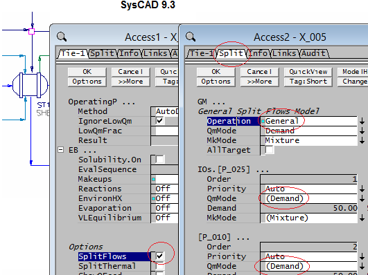
- If the user has a Tie in a vapour line connecting a Steam source, e.g. a Flash Tank, to a steam sink, e.g. a Shell and Tube Heat Exchanger, then the Tie must have the 'Split Flow' enabled and the GM operation = 'General'. The split to the line between the steam source and sink must always be in 'Demand' mode on the GM page for the Flash Train to work.
- The Digestion Projects, Flash Train Project, Evaporator Flash Train Project and Mechanical Vapour Recompression (MVR) Project, which are distributed with SysCAD in the Examples Folder, are some of the projects that demonstrate the use of a Flash Train in SysCAD.
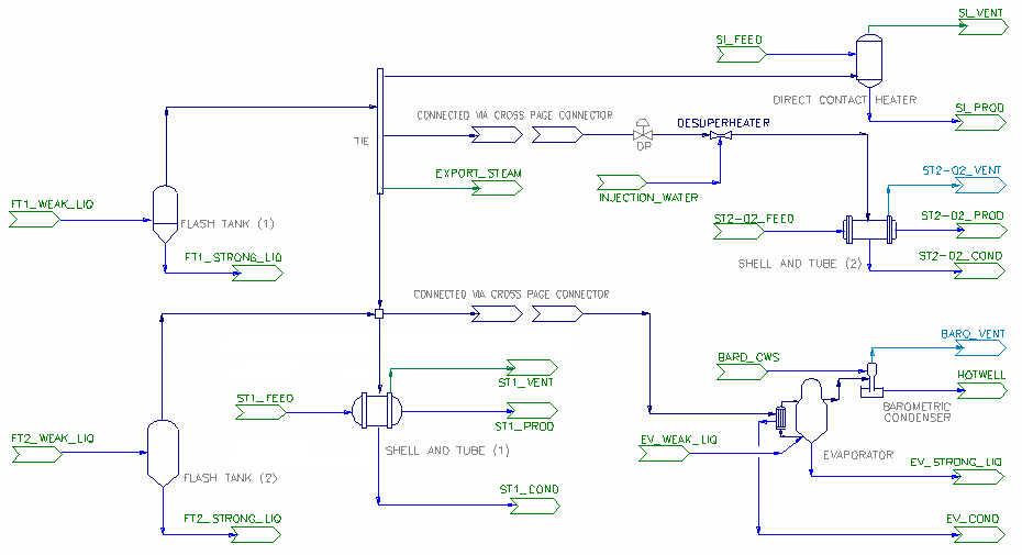
The diagram below shows an example of process units connected in such a way as to form four individual Flash Trains. These are NOT the only configurations for a Flash Train.
Diagram
The diagram shows an example of flash train network. The process units and lines shown in dark blue indicate the Flash train network formed. The different sections of the diagram can represent models on different flowsheets.
Not all of the above units need to be inserted for SysCAD to configure a Flash Train. If a Flash Tank is connected to a Shell and Tube Heat Exchanger, a Direct Contact Heat Exchanger or a Barometric Condenser, SysCAD will automatically form a Flash Train.
Inputs and Outputs
The Flash Train does not have configurable Inputs or Outputs. The user must connect the required Inputs and Outputs on each individual unit.
Model Theory
The theory for each individual unit is described in the documentation (see the relevant sections for the units that can comprise a Flash Train).
The object of the Flash Train is to emulate a plant system without having to hard-wire the temperatures and pressures of each individual unit. The Flash Tanks within the Flash Train will attempt to produce sufficient steam to satisfy the demands of the connected units. For example, if the vapour line from the Flash Tank is connected to a Shell and Tube Heat Exchanger, then the heat exchanger will 'demand' a certain amount of steam to meet its duty for the given heat exchanger area. SysCAD will adjust the pressure in the flash tank in an attempt to produce sufficient steam to exactly satisfy the Heat Exchanger.
Units that can comprise a Flash Train
|
The main units that can be a steam source are: |
The main units that can be a steam sink (destination) are: |
The main units that can be included in a Flash Train steam line |
|
|
Note: If a Tie is inserted between two Flash Train units, the Flash train will be broken. To reform the flash train, do the following:
- Tick the SplitFlows (Split) option in the Tie
- on the "Split" tab page, set Operation to General
- for all links set QmMode to (Demand)
Effects of Pressure Drop and Heat Loss
By default, SysCAD flows assume no pressure drop in vapour line and no heat loss from equipment, this may cause values from the model to differ to those from the actual plant data.
- To include the pressure drop in vapour lines, user can input some pressure drop information in the Pipes. See Pipe - Pressure Drop for more information.
- Pressure drop in vapour line may change the saturation temperature of the flash vapour and reduce the LMTD for the connected heat exchanger.
- User may add in the pressure drops manually, or use Darcy method to calculate the pressure drop based on pipe and flow information.
- To include heat loss, user may turn on the relevant heat loss sub model for the model, for example, EHX for Flash Tank, EnvironHX for Shell and Tube 2 Heat Exchanger.
NOTE: When tuning the SysCAD model to test/plant data, it maybe necessary to include pressure drops and heat losses as it will affect the performance of the circuit.
Data Sections
The data sections for each unit within the Flash Train are described in detail elsewhere (see the relevant sections for the units that can comprise a Flash Train).
Hints and Comments
- The information in the Vapour Liquid Equilibrium (VLE) must be correct for the units to operate as required. If the VLE configuration requires information that is not available, then the flashing will not occur.
- If the Flash Train includes a Shell and Tube Heat Exchanger, the user must ensure that the area and heat transfer coefficients of the unit are correctly specified.
- The Flash Train attempts to simulate a real plant environment. Therefore, the connections are very important. If the user configures the connections such that the fluids would not flow in a real plant, then the Flash Train will not function correctly.
- The user can make use of the SysCAD display colours to easily identify the flash train. From Tools | General Options | Colours, switch on the Macro Model option.
- For more hints and troubleshooting, please see Troubleshooting Flash Trains.

