Example - 03UnitModels Projects 2
Navigation: User Guide ➔ Example Projects ➔ 03 UnitModels (Part 2)
Related Links: 03 UnitModels (Part 1)
Cooling Tower Project
Project Location
This is a Steady State project and is stored at:
..\SysCADXXX\Examples\03 UnitModels\Cooling Tower Example.spf
Features Demonstrated
- A simple project showing how to set up a Cooling Tower with makeup and losses.
- Shows the estimate calculation for the air flows required.
- Shows the use of Set Tag Controller.
- Shows the use of Simple Heater to transfer heat duty.
- Shows the use of Simple Heat Exchanger.
- Shows the use of Demand logic.
- Shows the use of Composition Fetch in a Feeder.
- Shows the use of Annotation Table.
Brief Description
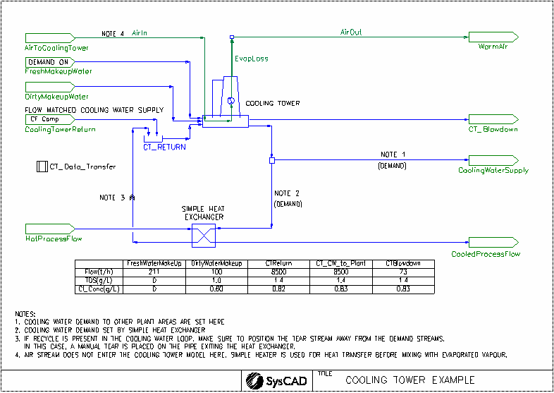
This project shows how to set up the Cooling Tower using the Merkel method.
- The project has a constant cooling tower return and a fixed (dirty) makeup water. Enough fresh makeup water is added to the cooling tower to counter for the various losses so that the cooling water out equals to the cooling water in (in terms of mass flow).
- The project also shows an estimate of the air flow and the estimated heat transfer with air.
Project Configuration
- The Project is set up as two separate sections, Cooling tower and Air flow estimate. The temperature of the cooling water is interlocked with the air temperature out. This is done via a Simple Heater downstream of the Air_In stream, where the HeatAvailable calculated in the cooling tower is transferred to the air stream.
- When setting up the cooling tower, AirWetBulbT, ApproachT/KaVL and LG_Ratio are important parameters to consider. See Cooling Tower for more information on the definition of these fields.
- Water loss due to Drift, cycles and evaporation are incorporated into the cooling tower.
- The cooling tower can estimate the required airflow needed to achieve the required cooling. The CT_Data_Transfer Set Tag Controller is used to transfer this air flow requirement to the AirToCoolingTower feeder. In this project, an optional air flow stream is added to mix with the evaporated vapour to give a air-water mixture stream.
- Part of the cooling water supply is used by the simple heat exchanger (SHX), the amount of water going to the SHX is calculated by the temperature requirements of the SHX using Demand logic.
- Demand logic is used to determine the amount of Fresh Makeup Water required to meet the total cooling water demand = main cooling water supply demand + cooling water required by simple heat exchanger. The FreshMakeupWater feeder has the "Demand.On" option enabled.
- Some impurities in the cooling tower feed are introduced in the DirtyMakeupWater feeder. In order to ensure that the impurities levels are maintained in the main cooling water supply stream, the Composition Fetch functionality is switched on in the CoolingTowerReturn feeder. Only the composition and flow are fetched as it is assumed that the temperature increases through the use of the cooling water throughout the plant.
- An Annotation Table has been added to show the TDS and chloride concentration in the main water streams.
Counter Current Washer Project
Project Location
This is a Steady State project and is stored at:
..\SysCADXXX\Examples\03 UnitModels\Counter Current Washer Example.spf
Features Demonstrated
- Shows how to set up a multi-stage (upto 6 stages) counter current washer circuit using the CCWasher unit operations.
- Shows how to set up a multi-stage (upto 6 stages) counter current washer circuit using the Washer unit operation, showing both mixing efficiency methods.
- Shows how to set up a multi-stage (upto 6 stages) counter current washer circuit using the Thickener unit operation, where washing efficiency is supplied via wash water addition.
- Shows how to set up Flocculant addition using makeups
- Shows how to set up the model to run scenarios (the project can run a minimum 2 and max 6 stages per train)
- Shows how to set up Annotation Table
- Shows how to set up Dynamic Bars
Brief Project Description
The aim of the sample project is to show the difference in the washer process models and how to connect them based on user requirements.
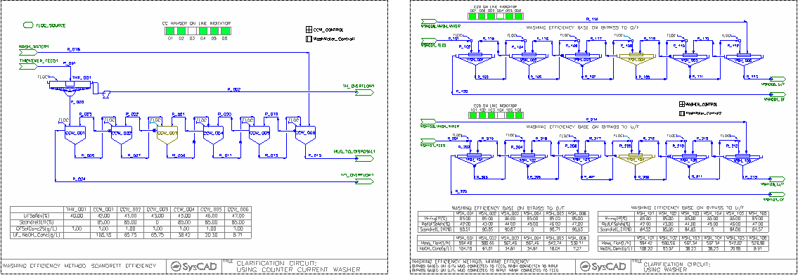
- CCWasher Flowsheet
- This flowsheet shows a 6-stage-Washing circuit using the CCWasher process model.
- Washer Circuit Flowsheet
- This flowsheet shows the same 6-stage-washing circuit using the Washer process model set up in two ways:
- Washing efficiency based on wash bypass to overflow and
- Washing efficiency based on liquid being trap in the mud.
- Thickener Flowsheet
- This flowsheet shows a 6-stage-Washing circuit using the Thickener process model.
Project Configuration
- CCWasher Flowsheet
- User must defined required underflow solids.
- The CCWasher unit operation allows the user to define the washing efficiency based on the Scandrett Efficiency. User must choose a species for this calculation. (The concentration of this species in the feed, overflow and underflow will be used to calculate the efficiency.) This should be the compound the washer is attempting to remove from the tailings stream.
- Some stages can be switched off in the PGM file. The first stage and last stage are always on.
- When stages are offline, the flocculant addition is stopped, and wash will report to the Overflow and Slurry input will report to the Underflow.
- Washer Circuit Flowsheet
- User must defined required underflow solids.
- User defines the required overflow solids.
- The Washer unit operation calculated the washing efficiency based on a MIXING Efficiency. The Mixing Efficiency can be based on either washing bypass directly to the overflow OR liquid being trap by the mud in the underflow. User must make a decision on which mixing efficiency method to use before drawing the circuit as the connections made to the unit operation would be different. See Washer for more information.
- The Washer Unit operation also shows the calculation of the scandrett efficiency, user may not specify a required scandrett efficiency directly from the unit, however, user can still achieve a certain scandrett efficiency if required by the use of a PID controller. (The use of PID controller is not demonstrated in this project.)
- Some stages can be switched off in the PGM file. The first stage and last stage are always on.
- When stages are offline, the flocculant addition is stopped, and wash will report to the Overflow and Slurry input will report to the Underflow.
- Thickener Flowsheet
- User must defined required underflow solids.
- Some stages can be switched off in the PGM file. The first stage and last stage are always on.
- When stages are offline, the flocculant addition is stopped.
- Since there is no separate input definition for the feed streams and all feed streams are mixed 100%, when turning off the stages, the feed streams have to be bypassed.
Included Excel Reports
CCD.xlsm
- This workbook is set up with 5 Case runs, showing the results of running 2 - 6 stages of washing.
- User can use the Excel Macro to Start SysCAD and create/run the Script file to obtain the results quickly.
Evaporator Flash Train Project
Project Location
This is a Steady State project and is stored at:
..\SysCADXXX\Examples\03 UnitModels\Evaporator Flash Train Example.spf
Features Demonstrated
- Setting up flash trains using Evaporator with embedded heat exchanger and Barometric Condenser.
- Use of the Solubility Functionality
Brief Project Description
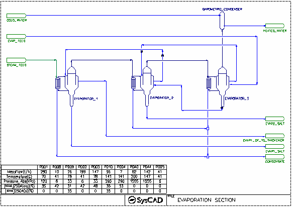
- This project shows a 3-Stage-Evaporator(crystalliser) circuit.
- This project uses constant feed for Liquor Feed, Steam and cooling water supply.
- The evaporators have embedded heat exchangers enabled
- Crystallisation is based on user defined solubility data.
- Evaporator underflow (crystallised material) is removed from the first and second stage. Third stage underflow is feed to the 2nd stage.
Project Configuration
Evaporator
- Evap Tab
- Select FlashTrain mode
- Specify minimum flash temperature for the unit (this will assist with pressure balance of the circuit)
- Select Solubility On
- Select Evaporator Heat Exchanger Option
- HX Tab - The Embedded Heat Exchanger has been defined, this includes the number of heat exchanges, size and heat transfer coefficient.
- Separ Tab - The solid liquid separator section has been defined with Overflow and Underflow solids requirement
- PC Tab - Select the solubility setting. NOTE the Solubility data is defined in the Species Database.
Barometric Condenser
- Set the approach temperature.
Flash Train Project
Project Location
This is a Steady State project and is stored at:
..\SysCADXXX\Examples\03 UnitModels\Flash Train Example.spf
Features Demonstrated
- Setting up flash trains using
- The use of PID controllers
- Connecting flows using Cross page connector. (This can be on the same flowsheet)
Brief Project Description
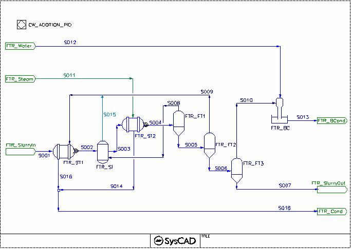
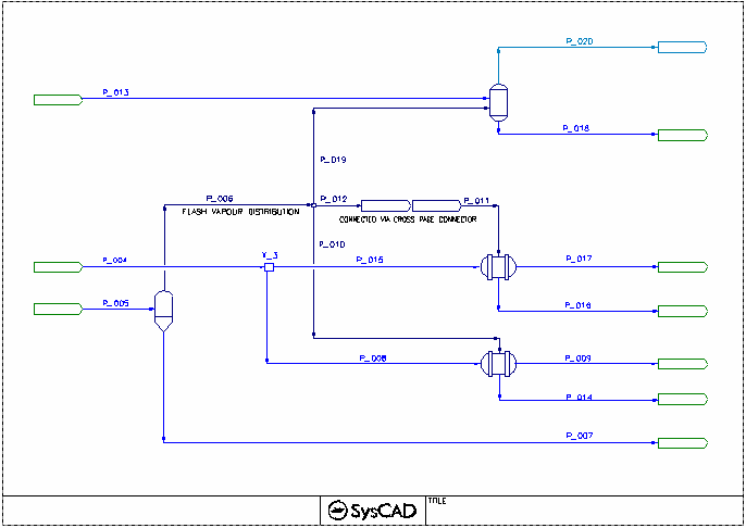
- The FlashTrain Flowsheet shows slurry is heated with Live steam prior to the flash stages, the hot flash vapour from the flash stages are being recycled to preheat the slurry. The barometric condenser is used to cool the last flash stage vapour.
- The FlashTrain2 Flowsheet demonstrates the flash vapour being used by three subsequent models. The steam demand will pass through cross page connections as shown on steam supplied to ST_2.
Project Configuration
- The flash train steam demand is based on Heater duty.
- Shell & Tube Exchangers must be operating in a Fully Condensing mode while in a flash train.
- On FlashTrain2 Flowsheet, the Tie X_1 has the Split Flow switched on and the it is operating on General Operation mode with all outputs on Demand mode. This allows SysCAD to demand the correct flash vapour from the flash tank based on the heater duties.
Mechanical Vapour Recompression MVR Example
Project Location
..\SysCADXXX\Examples\03 UnitModels\Mechanical Vapour Recompression MVR Example.spf
Features Demonstrated
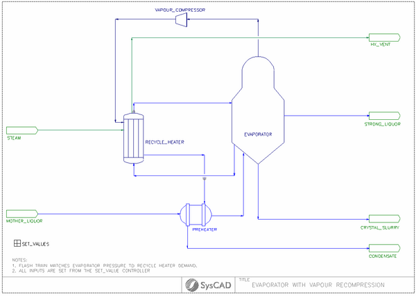
- Shows how to set up the Evaporator - gas Compressor - recycle heater configuration in SysCAD.
- Shows the Solubility Functionality.
- Shows the use of General Controller to input data into the project.
- Shows the use of PID controller.
Brief Project Description
- The gas compressor can be part of a flash train
- The evaporator is set up with external heat exchanger option.
- The evaporator can work as part of the flash train, where the pressure of the evaporated is dependent on the recycle heater capacity. (Flowsheet 01 Flash Train)
- If the evaporator pressure is set manually, user will need to either adjust the evaporator pressure or the heater size to balance the vapour flow. (Flowsheet 02 PID control)
Project Configuration
- Flash Train Mode
- In Flash train mode, the Evaporator pressure is auto-adjusted to meet the recycle heater demand. To configure the circuit in Flash Train mode, the following configuration is set:
- Compressor
- Fixed Pressure, using Isentropic calculation method.
- Evaporator:
- Evaporator Tab: Mode - Flash Train
- Separ Tab: Define the UF and OF solids requirements
- PC Tab: Select the Solubility function. The solubility data is entered in the Species Database.
- Recycle Heater:
- Method - CondensingSteam
- Condensing Method: Demand (UA)
- Demand Connection FlashTrain
- The condenser area and HTC information is supplied.
- Preheater:
- Method - Sensible HX (Liq/Liq)
- Condensing Method: Demand (UA)
- Demand Connection None (Manual)
- The preheater area and HTC information is supplied.
- Stand Alone Mode
- In Stand Alone mode, the Evaporator pressure is fixed, the flash vapour may not be fully condensed if the supply is too high. In this case, user may need to add in a PID controller to adjusted pressure to meet the recycle heater duty. To configure the circuit in stand-alone mode, the following configuration is set:
- Compressor
- Fixed Pressure, using Isentropic calculation method.
- Evaporator:
- Evaporator Tab: Mode - Stand Alone (Manual), Operatating Pressure set to Required Pressure (RequiredP)
- Separ Tab: Define the UF and OF solids requirements
- PC Tab: Select the Solubility function. The solubility data is entered in the Species Database.
- Recycle Heater:
- Method - CondensingSteam
- Condensing Method: Demand (UA)
- Demand Connection None (Manual)
- The condenser area and HTC information is supplied.
- Preheater:
- Method - Sensible HX (Liq/Liq)
- Condensing Method: Demand (UA)
- Demand Connection None (Manual)
- The preheater area and HTC information is supplied.
- PID Controller
- Set up a PID controller to adjust the Evaporator Pressure so that the Heat Exchanger Duty is met.
Thermocompressor TVR Example
NOTE: This project has been updated in Build 139.35658.
Project Location
..\SysCADXXX\Examples\03 UnitModels\Thermocompressor TVR Example.spf
Features Demonstrated
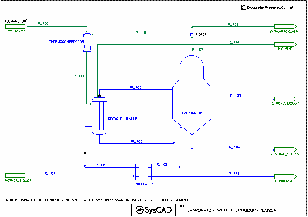
- Shows how to set up the Evaporator - Thermocompressor - recycle heater configuration in SysCAD.
- Shows the Solubility Functionality.
- Shows the use of General Controller to input data into the project.
- Shows the use of PID controller.
Brief Project Description
- The project demonstrates the use of Thermo Vapour Recompression (TVR) to reduce the energy required for an evaporating crystalliser.
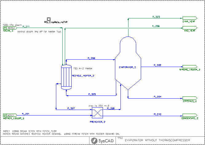
- Two flow sheets are included, both with identical feed and target conditions, and they share the same steam supply.
- The evaporator circulates slurry to an external recycle heater, maintaining a constant pressure in the evaporation vessel.
- Heat addition for both flow sheets is adjusted to achieve a target evaporation rate, removing water to reduce solubility and crystallise the product.
- The base case introduces live steam directly to the recirculating heater, while the TVR example uses live steam as the motive steam for the thermocompressor units.
- Both flow sheets incorporate a preheater for energy recovery from the recycle heater condensate.
- The TVR flow sheet requires a larger recycle heater area than the original case to ensure effective energy recovery.
- The TVR sheet offers the option to use a single TVR unit or two TVR units in series, with two TVR units in series being more efficient.
- The steam demand is reduced by approximately 20% with two TVR units operating in series and around 14% using a single TVR, compared to the base case.
- The TVR units are specified so that the suction load and final pressure are determined based on the required evaporation rate and heat exchanger performance.
- TVR units need to be designed and sized to suit each specific application, and they typically perform well only within a limited range of conditions.
- It is strongly recommended to work directly with a supplier during the design stage, and the thermocompressor in 1-D mode can be tuned to match the manufacturer’s data.
Project Configuration
- With Thermocompressor
- Thermocompressor
- Calculation Model:1D Model - S&K Data (Reference 1)
- Calculation Method: Discharge Pressure
- Demand.Connection: set to HP_Steam with demand on.
- Evaporator:
- Evaporator Tab: Mode - Stand Alone (Manual), Operatating Pressure set to Required Pressure (RequiredP)
- Separ Tab: Define the UF and OF solids requirements
- PC Tab: Select the Solubility function. The solubility data is entered in the Species Database.
- Recycle Heater:
- Method - CondensingSteam
- Condensing Method: Demand (UA)
- Demand Connection None (Manual)
- The condenser area and HTC information is supplied.
- Preheater:
- Method - Sensible HX (Liq/Liq)
- Condensing Method: Demand (UA)
- Demand Connection None (Manual)
- The preheater area and HTC information is supplied.
- PID Controller
- Set up a PID controller to adjust the Evaporator Vapour split to thermocompresor so that the Heat Exchanger Duty is met.
Reference:
- Bulletin 4F Supp, Schutte & Koerting, Performance Data on Jet Compressors
Reboiler Condenser Heat Exchanger Example
Project Location
This is a Steady State project available from Build 139.35244 and is stored at:
..\SysCADXXX\Examples\03 UnitModels\Reboiler Condenser Heat Exchanger Example.spf
Features Demonstrated
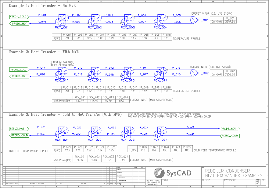
- Shows how to set up the Reboiler/Condenser Heat Exchanger (RCX) unit in SysCAD.
- Shows how to set up the Simple Heater, including optional side calculations for steam requirements.
Brief Project Description
- Three examples of heat transfer using the RCX unit:
- "Simple" heat transfer
- Heat transfer with Mechanical Vapour Recompression (MVR)
- Heat transfer with MVR demonstrating energy transfer from a colder stream to a hotter stream
- All examples use only water flows.
- While not demonstrated, note that reactions are possible within the hot and cold sides of the RCX unit.
Project Configuration
- Example 1 - Heat Transfer - No MVR:
- Similar to a Digestion Flash Train, a flow is preheated by recovered energy, then directly heated (e.g. with Live Steam), then cooled by transferring energy to the incoming stream.
- RCX units are configured with the same area and HTC on the hot and cold sides.
- Energy is transferred via the RCX units' internal Heat Transfer Fluid (HTF), in this case also water.
- Example 2 - Heat Transfer - With MVR:
- Same flow layout as Example 1.
- RXC units now include MVR (MVR.Options = Increase Temperature) to increase the saturation temperature of the HTF before the condensing (cold) side.
- Note the reduction in Live Steam duty.
- Example 3 - Heat Transfer - Cold to Hot Transfer (With MVR):
- Different flow layout to the previous examples, but the same RCX configuration as Example 2 (with MVR).
- Heat transfer between two independent streams. Demonstrates novel application of RCX with MVR to transfer energy from a colder stream to a hotter stream.
- Note that the hot stream becomes hotter, and the cold stream becomes colder.
Solvent Extraction Project
Project Location
..\SysCADXXX\Examples\03 UnitModels\Solvent Extraction Example.spf
Features Demonstrated
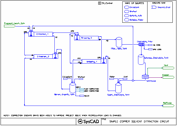
- Closed circuit Solvent Extraction and Electrowinning.
- The use of the mixer-settler unit operation for extraction and stripping.
- The use of isotherm in the mixer-settler unit operation.
- The use of Makeup Source and Makeup Block (MU) for extractant, organic, acid and water.
- The use of Discard Sink and Discard Block (DB)
- The use of PID Controllers.
Brief Project Description
- Pregnant leach solution is passed through 2 extraction stages where valuable metals are extracted using organic.
- The loaded organic is then stripped with an acidic solution in 2 stages to recovery the metal to the aqueous phase.
- The stripped solution is then sent to electrowinning to recover the metal and regenerate some acid to be used as the stripping solution.
- This is a close circuit operation. Bleed for the electrolyte stream comes from Electrolyte filter Crud removal; bleed for the organic circuit comes from the crud removal.
Project Configuration
- Setting up Solvent Extraction Unit:
- SeparMethod: individual phase to organics - User may specify separation density or separate based on individual phases
- Reactions: User may define reactions to change the phase (i.e. form aqueous to organic or vice versa).
- Method: User may select to Manually control the reactions or use the Isotherm to auto adjust the Reaction Extent of the first reaction in the reaction block. For example:
- The Extraction stage (Extraction_1) shows the use of isotherm. The isotherm is entered into the access window manually to represent the extraction rate for the first reaction, in this case, CuSO4(aq). When the isotherm is in use, the reaction extent for the first reaction is set from the isotherm.
- The Stripping stage (Stripping_2) shows the use of isotherm. The isotherm is entered into the access window manually to represent the stripping rate for the first reaction, in this case, R2Cu(o). When the isotherm is in use, the reaction extent for the first reaction is set from the isotherm.
- If more than one reaction is present, then the remaining reaction extents are manually specified by the user.
- Setting up the Organic Circuit
- Two Make up sources and make up blocks are used in the Barren Organic Tank to
- maintain a required organic flow for the circuit.
- add in enough extractant to give the organic stream the correct composition.
- The two make up blocks will be evaluated in sequence, therefore the order of these two blocks are important, make sure the flowrate is adjusted first, then the composition second.
- Discard blocks have been added to assist with flow reduction when needed.
- Setting up the Spent Electrolyte Circuit
- Two Make up sources and make up blocks are used in the Spent Electrolyte Tank to
- maintain a required aqueous flow for the circuit (based on a required organic/aqueous ratio set by the PID controller for stripping_1 stage. In this case, it is 1:1 volume based.)
- maintain the correct acid concentration.
- Once again the order of these two blocks are important, make sure the flowrate is adjusted first, then the concentration second.
- Setting up Bleeds
- The bleed streams are important if the circuit is to be used for flowrate analysis. Without the bleeds in place, recirculating loads cannot be reduced.
- The bleed of electrolyte is done via the filter.
- The bleed of organic is done via Crude removal.
- The organic bleed is done via discard sinks.
- Discards
- Discard Sink and Discard Block (DB) blocks are included to handle the recirculation flow changes for the organic loop.
- For the barren organic tank, flow increase will be added via the makeup blocks and flow decreases will be handled via the discard blocks.
- The Electrolyte filter are also set up with discard blocks to discard organic with aqueous entrainment to the same discard sink.
Included Excel Report
- Example project criteria report
- Reactions report
- Mass Balance
- Stream Report
