Digestion Projects
Jump to navigation
Jump to search
Navigation: User Guide ➔ Example Projects ➔ 10 Alumina: Digestion
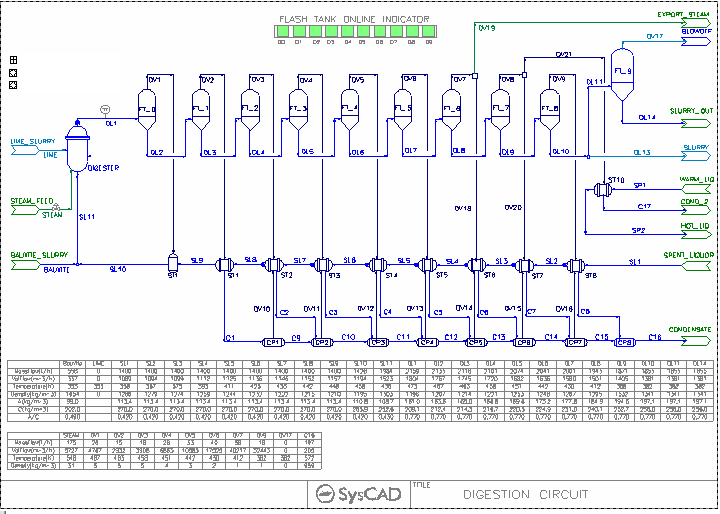
Example 1: Digestion with Direct Heating
Project Location
..\SysCADXXX\Examples\10 Alumina\Digestion Example.spf
Features Demonstrated
- Shows the use of Bayer3 properties model.
- Shows how to set up a multistage Flash Trains.
- Shows how to set up simple PGM files.
- Shows the use of Reaction files.
- Shows how to set up PID controls.
- Shows how to set up Annotation Blocks.
Brief Project Description
- The digestion reaction assumed to only occurs at the digestor.
- Steam is directly added to the digestor.
- The digestion circuit consist of 10 flash stages. Flash Vapour are sent to shell and tube heaters where they are fully condensed. The condensate is then reflashed to the next stage's pressure. The last condensate pot is modelled as a tank, as no flash will occur there.
- Steam is exported in stages 7&8.
- Two controllers are set up in the project:
- To control the steam addition to maintain the Digestor temperature.
- To adjust the bauxite charge to maintain a user defined DBO A/C ratio.
- Each set of Flash Tank - Heat Exchanger - Condensate Pot will form a Flash Trains where the unit operations will operate at the same pressure, the pressure of the flash train will be determined by SysCAD based on the heater performance.
- The flash Tank/Heat Exchanger/condensate pot set may be turned off to allow the model be run with fewer flash stages for feasibility analysis.
Project Configuration
- The Feed Composition
- Bauxite Feed uses wt% Al[OH]3(s), not Al2O3 (common Lab analysis). User may need to apply the appropriate conversion factors when specifying the Bauxite Feed composition.
- The Bayer Liquor maybe specified by the user manually using wt% (as demonstrated in the project) or via the DefineLiquor option, found under the Content Tab of the Feeder/XPG Connector.
- The live steam entering the Digestor vessel is condensed using the VLE sub model. User must specify an appropriate pressure for the Digestor to ensure steam can be condensed to achieve the required temperature. In this example, the pressure is set a lot higher than required, so that it can handle a range of temperature setpoints.
- The Digestion outlet DL1 has the EHX sub model switched on, this sub model is used to stablise the solution.
- The temperature of material leaving DL1 is set by the EHX sub model. This ensures the downstream flash tanks can solve quickly without temperature fluctuation.
- The temperature of material entering DL1 is adjusted by steam addition, using PID controller.
- When the project is solved, the DL1 EHX should have 0 energy flow (based on the tolerance settings)
- Heat Exchanger Configuration
- The Heat Exchanger must have the correct Heat Transfer Area and Heat Transfer Coefficient specified.
- The Heat Exchanger must be placed in the FullyCondensing mode.
- Exporting Steam configuration
- When a tie is added to a flash train, it will at first break the flash train configuration, user must change to configuration to re-form the flash train.
- Stage 7 export steam shows how to include only one stream in the flash train.
- Stage 8 export steam have both outlets included in the flash train.
Included Excel Reports
- Digestion.xlsm - this excel report shows how to use macro to run some quick scenarios via command script.
- DigestionEx.xls - this excel report show some basic report formats for the project, these include Stream, control and reaction report.
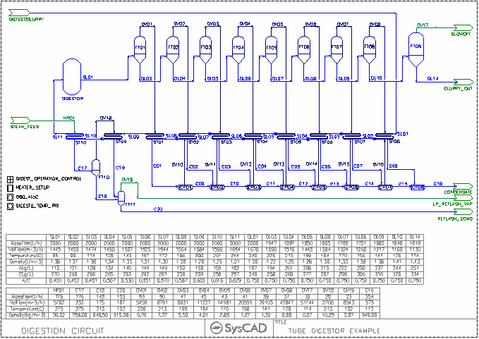
Example 2: Tube Digestion with Indirect Heating
Project Location
..\SysCADXXX\Examples\10 Alumina\Digestion with Tube Digestor Example.spf
Features Demonstrated
- Shows the use of Bayer3 properties model.
- Shows how to set up a multistage Flash Trains.
- Shows how to set up advance PGM files.
- Shows how to use the SetTag Controller to change configuration data for multiple units.
- Shows the use of Reaction files.
- Shows how to set up PID controls.
- Shows how to set up Annotation Blocks.
Brief Project Description
- Heaters used are Shell&Tube(2). This process model allows reaction to occur on the Tube side. In this example, Gibbsite dissolution occurs as material moves through the heater train. The heat balance will be affected by these reactions.
- The Gibbsite dissolution reaction extent in each heater stage is calculated and controlled via the Digestion_Operation_Control (PGM control). It is assumed that Gibbsite will fully dissolve above 150 dC.
- Steam is indirectly added to the digestor feed. Live steam condensate undergoes two flashing stages, which is used for preheating / steam export.
- The digestion circuit consist of 9 flash stages. Flash Vapour are sent to shell and tube heaters where they are fully condensed. The condensate is then reflashed to the next stage's pressure. The last condensate pot is modelled as a tank, as no flash will occur there.
- Two PID controllers are set up in the project:
- To control the steam addition to maintain the Digestor temperature.
- To adjust the bauxite charge to maintain a user defined DBO A/C ratio.
- Each set of Flash Tank - Heat Exchanger - Condensate Pot will form a Flash Train where the unit operations will operate at the same pressure, the pressure of the flash train will be determined by SysCAD based on the heater performance.
- The heater area and heater transfer coefficient is assumed to be the same for all heaters, user may adjust these values from the Heater_Setup Process Unit.(Set Tag Controller)
- The flash Tank/Heat Exchanger/condensate pot set may be turned off to allow the model be run with fewer flash stages for feasibility analysis.
Project Configuration
- The Feed Composition
- Bauxite Feed uses wt% Al[OH]3(s), not Al2O3 (common Lab analysis). User may need to apply the appropriate conversion factors when specifying the Bauxite Feed composition.
- The Bayer Liquor maybe specified by the user manually using wt% (as demonstrated in the project) or via the DefineLiquor option, found under the Content Tab of the Feeder/XPG Connector.
- The Digestion outlet DL1 has the EHX sub model switched on, this sub model is used to stablise the solution.
- The temperature of material leaving DL1 is set by the EHX sub model. This ensures the downstream flash tanks can solve quickly without temperature fluctuation.
- The temperature of material entering DL1 is adjusted by steam addition, using PID controller.
- When the project is solved, the DL1 EHX should have 0 energy flow (based on the tolerance settings)
- ShellTube(2) Heat Exchanger Configuration
- The Heats must have the correct Heat Transfer Area and Heat Transfer Coefficient specified.
- The live steam heater maybe placed in the stand alone condensingsteam mode (no demand calc)
- All other heater should be placed in the condensingsteam mode with Demand UA and Flash Train option.
Included Excel Reports
One demonstration excel reports are included in the project.
- TubeDigestion.XLS - this excel report show some basic report formats for the project, these include Input Criteria and simple overall balance, Stream data and reaction report.

