Reboiler/Condenser Heat Exchanger
|
NOTE: This feature is distributed with SysCAD but is currently in BETA. Please contact us ([email protected]) if you run into any issues using this model. This page is currently under development and details may change. Use with caution - we do not guarantee compatibility between different BETA versions. |
Navigation: Models ➔ Energy Transfer Models ➔ Reboiler/Condenser Heat Exchanger
Related Links: Reboiler Condenser Heat Exchanger Example
General Description
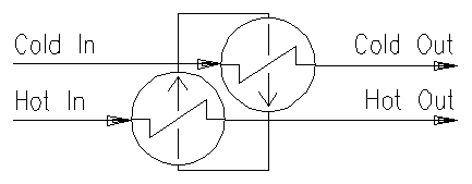
The Reboiler/Condenser Heat Exchanger (RCX) is used to transfer heat from one stream to another. The RCX Heater unit model is based on patented technology[1] and was developed with in association with the patent holder[2]. In principle, an internally-recirculating heat transfer fluid (HTF) transports heat from the "hot" stream to the "cold" stream, similar to a Heat Pipe (see Wikipedia). The HTF is in the shell side, while the hot and cold streams are in separate tube sides. The RCX Heater unit can be used in a single- or dual-shell arrangement as shown below.
- In the Hot Side (Reboiler), heat is transferred from the hot stream to the HTF, cooling the hot stream and boiling the HTF.
- The HTF vapour then reports to the Cold Side (Condenser) where energy is transferred to the cold stream, heating the cold stream and condensing the HTF.
- The condensed HTF is then returned to the Hot Side, completing the recycle.
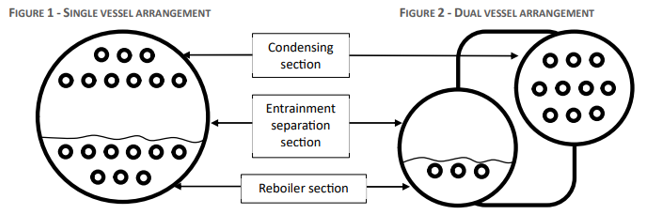
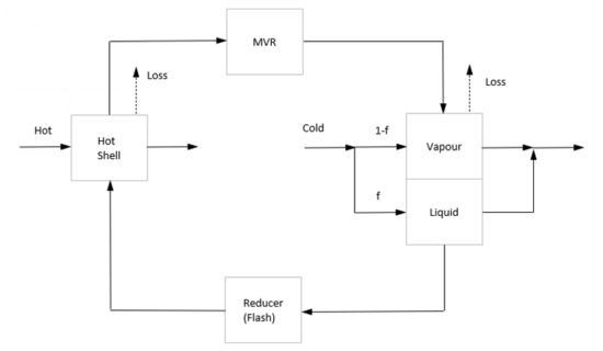
In a single-shell arrangement the HTF pressure is constant. However, in a dual-shell arrangement as shown to the right, the HTF vapour between Hot Side and Cold Side can be subject to mechanical vapor recompression (MVR) to increase pressure, temperature and boiling point. In this arrangement, the Hot and Cold shell sides operate at different pressures. It is then possible for the "hot" stream (the heat source used to boil the HTF) to be colder than the "cold" stream (the heat sink used to condense the HTF), thereby transferring energy from a colder stream to a hotter stream!
In dual-shell arrangement, the HTF may also be subcooled by partially flooding the Condenser, in order to minimise any flashing which would occur through the Reducer valve separating the Cold and Hot Sides. Due to adiabatic inefficiency, energy is added to the system via MVR. Energy is also lost from the system due to ambient heat loss from the shell(s).
Diagram
Inputs and Outputs
| Label | Required Optional |
Input Output |
Number of Connections | Description | |
| Min | Max | ||||
| Hot In | 1 Required | In | 1 | 10 | The stream inlet to the Hot Side (Reboiler). |
| Cold In | 1 Required | In | 1 | 10 | The stream inlet to the Cold Side (Condenser). |
| Hot Out | 1 Required | Out | 1 | 1 | The stream outlet from the Hot Side (Reboiler). |
| Cold Out | 1 Required | Out | 1 | 1 | The stream outlet from the Cold Side (Condenser). |
Note that the recirculating HTF (Heat Transfer Fluid) is an internal flow and has no connections.
Behaviour when Model is OFF
If the user disables the unit, by un-ticking the On tick box, then the following actions occur:
- All streams connected to the 'Hot In' inlet will flow out of the 'Hot Out' outlet with no temperature or phase change
- All streams connected to the 'Cold In' inlet will flow out of the 'Cold Out' outlet with no temperature or phase change
- Any sub-models, such as Reaction Block, will not occur
- No energy exchange will occur
So basically, the unit will be 'bypassed' without the user having to change any connections.
Model Theory
The KCX Heater is a composite model comprised of multiple embedded unit models. While this unit model could be built in SysCAD from its component parts and the HTF recirculation loop, such a model would be complex to implement, difficult to robustly control, and cumbersome to use within project flowsheets. As such, the implementation as a composite model with internal iterative solver and control provides a robust standalone unit model.
The user specifies the following:
- Hot and cold streams (by Pipe connection)
- HTF component (internally recirculating shell-side species, no SysCAD stream connection required)
- Hot and Cold Side tube details:
- HTC
- Area
- Reactions
- Pressure drop
- Hot and Cold Side heat loss from shell
- Physical layout:
- Single- or dual-shell
- MVR (if dual-shell):
- Temperature or pressure change
- Mechanical and adiabatic efficiencies
- Subcooling (if dual-shell):
- HTC
- Flooded fraction of Cold Side area
The RCX Heater unit model uses internal iterative calculations to determine the required HTF temperature(s), pressure(s) and mass flowrate to satisfy the energy balance. This uses the nominated HTF component thermodynamic data from the Species Database. Note that both the liquid and gas phases of the HTF component must be defined.
Internally, both the Hot and Cold Sides use the same LMTD heat transfer logic as any heater. Tube-side reactions (including heat of reaction) and pressure drop are evaluated before heat exchange. The RCX Heater iterative solver is bound by the following requirements:
- Energy transfer from Hot Stream by LMTD = Energy absorbed in vaporising HTF at Hot Side saturation temperature
- Energy transfer to Cold Slurry by LMTD = Energy released by condensing HTF at Cold Side saturation temperature
- Energy into the system = Energy out of the system (this is complicated by MVR adiabatic inefficiency, tube-side heat of reaction, and ambient heat loss)
This iterative calculation also includes checks and stops for various forbidden/unsolvable cases, such as Shell-Tube temperature crossover, HTF pressure below minimum allowance, and HTF temperature approaching the component's critical temperature.
Data Sections
The default access window consists of several sections:
- HeaterKX tab - This first tab contains general information relating to the unit.
- Results tab - This tab contains unit results and intermediate values used for calculation of energy balance.
- HotRB - Optional tab, only visible if the Reactions are enabled on the Hot side. Please note that the RCX Heater unit will IGNORE any Source, Sink or HX in the reaction file.
- ColdRB - Optional tab, only visible if the Reactions are enabled on the Cold side. Please note that the RCX Heater unit will IGNORE any Source, Sink or HX in the reaction file.
- QHotFeed - Optional tab, only visible if ShowQHotFeed is enabled. This and subsequent tab pages, e.g. QHotFeed.. and Sp, shows the properties of the mixed stream as the feed to the Hot side.
- QColdFeed - Optional tab, only visible if ShowQColdFeed is enabled. This and subsequent tab pages, e.g. QColdFeed.. and Sp, shows the properties of the mixed stream as the feed to the Cold side.
- QHotProd - Optional tab, only visible if ShowQHotProd is enabled. This and subsequent tab pages, e.g. QHotProd.. and Sp, shows the properties of the product stream from the Hot side.
- QColdProd - Optional tab, only visible if ShowQColdProd is enabled. This and subsequent tab pages, e.g. QColdProd.. and Sp, shows the properties of the product stream from the Cold side.
- Info tab - Contains general settings for the unit and allows the user to include documentation about the unit and create Hyperlinks to external documents.
- Links tab, contains a summary table for all the input and output streams.
- Audit tab - Contains summary information required for Mass and Energy balance. See Model Examples for enthalpy calculation Examples.
RCX Heat Exchanger Page
Unit Type: HeaterKX - The first tab page in the access window will have this name.
| Tag (Long/Short) | Input / Calc | Description / Calculated Variables / Options |
| Tag | Display | This name tag may be modified with the Change Tag option. |
| Condition | Display | "OK" if no errors/warnings, otherwise lists errors/warnings. |
| ConditionCount | Display | The current number of errors/warnings. If condition is OK, returns 0. |
| GeneralDescription / GenDesc | Display | An automatically generated description for the unit. If text is entered in the 'EqpDesc' field on the Info tab (see below), this is displayed here. Otherwise, SysCAD will display the UnitType or SubClass. |
| Requirements | ||
| On | Tick Box | Switches the RCX Heat Exchanger on/off. |
| Shell ... | ||
| HTF.Component | List Box | Selection from list of HTF (Heat Transfer Fluid) component. Any component with species in both the gas and liquid phases found in the project species configuration will appear in this list. Water is always available as H2O(l) and H2O(g) are always required species in project configuration. |
| HTF.LiquidSp | Calc | The liquid species of the selected HTF component. |
| HTF.VapourSp | Calc | The gas species of the selected HTF component. |
| HTF.CriticalT | Calc | The critical temperature of the selected HTF component. |
| Layout | ||
| MVR.Option | None | No MVR (Mechanical Vapour Recompression) is included. This allows selection between one or two shell operation. |
| Increase Pressure | MVR is enabled with control over the increase in HTF saturation pressure (saturation temperature change is a result). | |
| Increase Temperature | MVR is enabled with control over the increase in HTF saturation temperature (saturation pressure change is a result). | |
| TwoShells | Check Box | Only available if MVR.Option = None. If this is true, Hot and Cold sides are separate shells with independent heat loss options. If this is false, the unit has a single shell and heat loss is only available for the Hot side. |
| Subcooling | None | No sub-cooling of the HTF inside the Cold side shell. |
| Flood Fraction | Sub-cooling is enabled within the Cold side shell by partial flooding. | |
| FloodFraction | Input | The fraction of Cold side heat transfer area which is flooded. |
| LiquorHTC | Input | The heat transfer coefficient of the flooded Cold side tubes (i.e. between the Cold side stream and the liquid phase HTF). |
| HotSide / ColdSide ... - Note that the Hot (Reboiler) and Cold (Condenser) side input fields are identical. | ||
| UserHTC | Input | The heat transfer coefficient of this side's heat transfer area. |
| Layout | Overall | The heat transfer area is defined by area input. |
| Tube Detail | The heat transfer area is defined by tube sizing and layout. This is calculated by [math]\displaystyle{ \pi \times TubeOD \times Tubes \times Passes \times PassLength }[/math] | |
| UserArea | Input | Available if Layout = Overall. The defined heat transfer area for this side. |
| TD.TubeOD | Input | Available if Layout = Tube Detail. The diameter of the heat transfer tubes. |
| TD.Tubes | Input | Available if Layout = Tube Detail. The number of heat transfer tubes. |
| TD.Passes | Input | Available if Layout = Tube Detail. The number of passes of heat transfer tubes. |
| TD.PassLength | Input | Available if Layout = Tube Detail. The length of each pass of heat transfer tubes. |
| PressDropReqd | Input | The required pressure drop through the tube side. Note that this is a pressure change inside the tubes and does not affect the pressure of the HTF. |
| HeatLoss.Method (Not available for ColdSide if Single Shell.) |
None | No heat loss. |
| Fixed HeatFlow | Heat loss is a user input power value. | |
| Fractional | Heat loss is calculated as a fraction of heat transfer within this side. | |
| Loss to Ambient | Heat loss is calculated using shell surface area, HTC and external temperature. | |
| HeatLoss.HeatFlowReqd | Input | Available if HeatLoss.Method = Fixed HeatFlow. The required heat loss from the shell of this side. |
| HeatLoss.FracReqd | Input | Available if HeatLoss.Method = Fractional. The required fraction of heat transfer as heat loss from the shell of this side. |
| Shell.Diameter | Input | Available if HeatLoss.Method = Loss to Ambient. The shell diameter of this side. Used for calculating shell area. |
| Shell.Length | Input | Available if HeatLoss.Method = Loss to Ambient. The shell length of this side. Used for calculating shell area. NOTE: This is the same value as TD.PassLength. Changing one will change the other. |
| Shell.SurfaceArea | Calc | Available if HeatLoss.Method = Loss to Ambient. The shell surface area of this side. Calculated as [math]\displaystyle{ /pi /times Shell.Diameter /times / Shell.Length }[/math]. Note that the "end caps" are not considered. |
| Shell.HTC | Input | Available if HeatLoss.Method = Loss to Ambient. The heat transfer coefficient of the shell (i.e. between the HTF and the external conditions). |
| AmbTOverride | Input | Available if HeatLoss.Method = Loss to Ambient. Optional override of the ambient temperature. To use the project environment ambient temperature set this to * (undefined). |
| Ambient_T | Calc | Available if HeatLoss.Method = Loss to Ambient. The external temperature used for heat loss calculation from the shell. This is equal to the project environment ambient temperature if AmbTOverride is undefined. |
| Reactions | On | Enables Reaction Block (RB) for this side. Reactions are applied inside the tubes and do not affect the HTF. Note that the RCX Heater unit will IGNORE any Source, Sink or HX in the reaction file. |
| Off | No reaction for this side. | |
| MVR ... | ||
| Option | None | No MVR (Mechanical Vapour Recompression) is included. This allows selection between one or two shell operation. |
| Increase Pressure | MVR is enabled with control over the increase in HTF saturation pressure. | |
| Increase Temperature | MVR is enabled with control over the increase in HTF saturation temperature. | |
| dT_Reqd | Input | Available if Option = Increase Temperature. The required change in HTF saturation temperature across the MVR. Pressure change is a result. |
| dP_Reqd | Input | Available if Option = Increase Pressure. The required change in HTF saturation pressure across the MVR. Temperature change is a result. |
| AdiabaticEfficiency / AdiabaticEff | Input | The adiabatic efficiency of the MVR. Inefficiency is added as heat to the HTF. |
| MechanicalEfficiency / MechanicalEff | Input | The mechanical efficiency of the MVR. This is used for calculation of the overall MVR compressor power requirement and has no effect on the HTF. |
| Specified Configuration - This will show a text description of the physical configuration. E.g. Two Shells, Mechanical Vapour Recompression. | ||
| Options | ||
| ShowQHotFeed | Tick Box | QHotFeed and associated tab pages (e.g. Sp) will become visible, showing the properties of the combined Hot stream feed flow. See Material Flow Section. This will be prior to any sub-model actions (e.g. Reactions). |
| ShowQColdFeed | Tick Box | QColdFeed and associated tab pages (e.g. Sp) will become visible, showing the properties of the combined Cold stream feed flow. See Material Flow Section. This will be prior to any sub-model actions (e.g. Reactions). |
| ShowQHotProd | Tick Box | QHotProd and associated tab pages (e.g. Sp) will become visible, showing the properties of the combined Hot stream outlet flow. See Material Flow Section. |
| ShowQColdProd | Tick Box | QColdProd and associated tab pages (e.g. Sp) will become visible, showing the properties of the combined Cold stream outlet flow. See Material Flow Section. |
| User Warning Limits | ||
| TrackHTF.MinP | Tick Box | Generate a warning message if the calculated HTF pressure falls below a specified value. E.g. to prevent ingress of ambient air. |
| TrackHTF.CriticalT | Tick Box | Generate a warning message if the HTF temperature approaches the critical temperature of the component. |
| HTF.MinP | Input | Available if TrackHTF.MinP is ticked. The minimum pressure allowed for the HTF. Note that the unit will still solve, but a warning will be generated. |
| HTF.ApproachCriticalT | Input | Available if TrackHTF.CriticalT is ticked. The dT approach to the critical temperature. Note that in this range the unit will still solve, but a warning will be generated. Above the critical temperature, the unit will not solve and will always give an error. |
| Convergence ... | ||
| RelTol | Input | The relative tolerance for the internal iterations to find HTF saturation temperature (internal iterations will stop when the step change is less than this value). |
| MaxIterCount | Input | The maximum number of internal iterations on a single Solver step for the internal convergence loop. |
| IterCount | Calc | The actual number of internal iterations used on the previous Solver step. |
| RelError | Calc | The relative error of the last internal iteration at end of the previous Solver step. (This must be lower than RelTol for the model to be "solved".) |
Results Page
This page provides the results of the unit model calculations, including details for the internal recirculating HTF stream.
| Tag (Long/Short) | Input / Calc | Description / Calculated Variables / Options |
| Specified Configuration - This will show a text description of the physical configuration. E.g. Two Shells, Mechanical Vapour Recompression. | ||
| HotSide / ColdSide ... - Most Hot (Reboiler) and Cold (Condenser) side result fields are identical. For the ColdSide, this applies to tubes in the condensing HTF vapour space only (i.e. excludes subcooling, if enabled). | ||
| HTC | Calc | The Heat Transfer Coefficient used for this side. |
| Area | Calc | The Area used for this side. |
| TemperatureIn / Ti | Calc | The temperature of the combined streams into the tubes for this side (i.e. Hot In or Cold In temperature). |
| TemperatureOut / To | Calc | The temperature of the stream out of the tubes for this side (i.e. Hot Out or Cold Out* temperature). *For ColdSide, if subcooling is enabled, this is the temperature out of HTF vapour space only. |
| LMTD | Calc | The Log Mean Temperature Difference for this side. |
| DeltaT / dT | Calc | The change in temperature through the tubes for this side. |
| PressureIn / Pi | Calc | The pressure of the combined streams into the tubes for this side (i.e. Hot In or Cold In pressure). |
| PressureChange / dP | Calc | The change in pressure through the tubes for this side. |
| PressureOut / Po | Calc | The pressure of the stream out of the tubes for this side (i.e. Hot Out or Cold Out pressure). |
| MassFlow / Qm | Calc | The mass flow through the tubes for this side. |
| HeatTransfer / HX | Calc | The heat transfer with HTF for this side. [math]\displaystyle{ HX = HTC \times Area \times LMTD }[/math] ([math]\displaystyle{ = UA \times LMTD }[/math]) HotSide: This is the heat flow from the Hot stream to vaporise HTF. (= A) ColdSide: This is the heat flow from condensing HTF to the Cold stream. (= D) |
| HeatLoss | Calc | Environmental heat loss from the shell of this side. HotSide: Heat loss from Hot shell. (= B) ColdSide: Heat loss from Cold shell. (= E) (Not available for Single Shell) |
| RB.HeatOfReaction / RB.HOR | Calc | (Only visible if Reactions are enabled) Heat of reaction within the tubes for this side. |
| RB.TemperatureOut / RB.To | Calc | (Only visible if Reactions are enabled) The temperature of the combined streams into the tubes after evaluation of reactions (RB), before any heat exchange. |
| HTF.CondensingPower | Calc | (ColdSide only, visible if Two Shell operation) Power from HTF condensation at cold side HTF conditions. (= D + E) |
| HTF.FlashPower | Calc | (ColdSide only, visible if Two Shell operation) Excess energy released flashing HTF condensate to hot side HTF conditions. (= F) |
| HTF.FlashMassFlow / HTF.FlashQm | Calc | (ColdSide only, visible if MVR is online) Mass flow of vapour generated in flash to hot side HTF conditions. |
| Shell ... (Hot side shell if Two Shell operation) | ||
| HTF.TransferPower / HTF.Power | Calc | Total power transfer to HTF. (= A - B + F) |
| HTF.Temperature / HTF.T | Calc | HTF temperature. |
| HTF.Pressure / HTF.P | Calc | HTF saturation pressure. |
| HTF.SatT@P | Calc | HTF saturation temperature at pressure. (= HTF.T) |
| HTF.MassFlow / HTF.Qm | Calc | HTF recirculating mass flowrate. |
| HTF.LatHtVap | Calc | HTF latent heat of vaporisation at shell temperature and pressure. |
| MVR ... (only available if MVR is online) | ||
| EntropyIn / Si | Calc | HTF entropy at MVR inlet temperature and pressure. |
| PressureIn / Pi | Calc | HTF pressure at MVR inlet (= HTF.P) |
| TemperatureIn / Ti | Calc | HTF temperature at MVR inlet (= HTF.T) |
| IdealPower | Calc | Required MVR power input to HTF vapour at 100% adiabatic efficiency to achieve specified dT or dP. |
| Power | Calc | Actual MVR power input to HTF vapour at defined adiabatic efficiency. (= C) |
| InputPower | Calc | Power input to MVR compressor at defined mechanical efficiency. |
| PressChange / dP | Calc | Pressure change through MVR. |
| PressureOut / Po | Calc | HTF pressure at MVR outlet. |
| SatT@P | Calc | HTF saturation temperature at MVR outlet pressure. |
| TemperatureOut / To | Calc | HTF temperature at MVR outlet. |
| EntropyOut / So | Calc | HTF entropy at MVR outlet temperature and pressure. |
| Subcool ... | ||
| SubcoolingPower / Power | Calc | Power transfer for subcooling of HTF condensate to Cold stream. (= G) |
| HTF.Temperature / HTF.T | Calc | Temperature of subcooled HTF condensate. |
| Flooded.MassFlow / Flooded.Qm | Calc | Mass flow of Cold stream used for subcooling. |
| Flooded.TemperatureOut / Flooded.To | Calc | Outlet temperature of Cold stream used for subcooling. |
| ColdOutlet.TemperatureOut / ColdOutlet.To | Calc | Outlet temperature of the combined Cold stream (i.e. Cold Out temperature). |
| ColdOutlet.DeltaT / ColdOutlet.dT | Calc | The overall Cold stream temperature change. |
| Results | ||
| EnergyBalance | Calc | The overall energy balance, this should be zero when solved. (= A - B + C - D - E - F - G) |
| HeatFlow | Calc | Total external heat flow to the RCX Heater unit. (= - B + C - E) |
| HTF.LiqEnthalpy | Calc | HTF liquor phase enthalpy at HTF.T and HTF.P (HotSide). |
| HTF.VapEnthalpy | Calc | HTF gas phase enthalpy at HTF.T and HTF.P (HotSide). |
| HTF.VapEnthalpy_MVR | Calc | HTF gas phase enthalpy at MVR.To and MVR.Po (MVR outlet / ColdSide feed). |
| HTF.LiqEnthalpy_Cond | Calc | HTF liquor phase enthalpy at MVR.SatT and MVR.Po (ColdSide). |
| HTF.LiqEnthalpy_Sub | Calc | HTF liquor phase enthalpy at SubCool.HTF.T and MVR.P (ColdSide subcooling). |
Adding this Model to a Project
Add to Configuration File
Sort either by DLL or Group:
| DLL: | HeatExchange.dll |
→ | Units/Links | → | Heat Transfer: Reboiler/Condenser Heat Exchanger | |
| or | Group: | Energy Transfer |
→ | Units/Links | → | Heat Transfer: Reboiler/Condenser Heat Exchanger |
See Model Selection for more information on adding models to the configuration file.
Insert into Project Flowsheet
| Insert Unit | → | Heat Transfer | → | Reboiler/Condenser Heat Exchanger |
See Insert Unit for general information on inserting units.
Example Project
References
- Clegg, R.L. (2020) "Heat Exchanger", United States Patent Application US 2020/0284514 A1
- Note that the technology is patented or patent-pending in various global regions, including Australia, China (ZL 2018800578696), Europe, West Africa and U.S (US20200284514A1).
- Clegg, R.L. (July 2020) Private Correspondence between KWA Kenwalt Australia and Refina