Model Selection
Navigation: User Guide ➔ Edit Command Summary ➔ Project Configuration (cfg File) ➔ Model Selection
| Project Configuration (Main Page) |
Edit Configuration (Step 1) | Edit Configuration (Step 2) | |||||
|---|---|---|---|---|---|---|---|
| Model Selection | General Configuration | Species Configuration | Species Properties Configuration | Calculation Configuration | TCE Configuration | Size Configuration | |
Latest SysCAD Version: 25 February 2025 - SysCAD 9.3 Build 139.37016
Edit Configuration Step 1 of 2
The first step is to select the SysCAD unit models to be used in the project. User may need to check the unit models from time to time due to:
- New Models may have been added through SysCAD version change, to use these new models, user must select them in this step of the Edit Configuration file.
- Some models are restricted by license agreement. If the project is to be shared with third parties, please ensure all parties involved have the correct license to access all unit models selected, otherwise user may need to de-select the "restricted" model and make modification to the project before sharing of the project with parties with less license options.
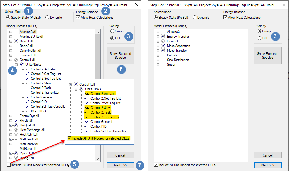
The image below shows 2 different views of the Model Selection access window, as explained in the table below:
| Number | Setting/Selection | Description |
| Solver Mode | The user must choose either Steady-State (ProBal) or Dynamic (may depend on license options). This selection can also be made on the second configuration page. Refer to Solver Modes for more information. | |
| Energy Balance (New for Build 139) |
The user must choose to either Allow Heat Calculations or not. This selection can also be made on the second configuration page. Refer to Energy Balance for more information. | |
| Sort By | You may view the available models by:
NOTE: Not all models are available to all users. Please check your license agreement to see what models are available for use. Refer to Models for a list of the standard models available to users with standard licenses. | |
| Model Libraries | You may select (marked by the blue tick) or de-select models as required. Each dll (Dynamic Link Library) group shown in the above window contains a number of models, as indicated by the + box on the right hand side. By clicking on this + box, the user can expand the tree view and see the models available in each dll group. This is shown for the Control1.dll group.
| |
| Include All Unit Models (New for Build 138) |
When enabled, all unit models for dlls which have at least one unit model selected will be automatically included. This will also apply to future new unit models for a dll automatically being available.
The image above shows the same configuration, firstly without the Include All Unit Models option selected and then in the inset, with the Include All Unit Models option selected. This shows that four unit models which belong to the Control1 dll and were not originally included, are included when the Include All Unit Models option is enabled. | |
| Show Required Species | Certain unit models require specific species to be present for the models to operate correctly. These include:
Once you have selected the models for the project you may click on the Show Required Species button and you will see a list of all of the species that MUST be included in the project. If any of the listed species are NOT included in the project configuration, then SysCAD will give you a warning. After the Next>>> button Notes:
|
Edit Configuration Step 2 of 2
Based on the models selected, a second dialog box with variable number of tab pages will appear for further customisation when the Next>>> button is pressed. Refer to General Configuration.
