General Configuration
Navigation: User Guide ➔ Edit ➔ Project Configuration (cfg File) ➔ General Configuration
| Project Configuration (Main Page) |
Edit Configuration (Step 1) | Edit Configuration (Step 2) | |||||
|---|---|---|---|---|---|---|---|
| Model Selection | General Configuration | Species Configuration | Species Properties Configuration | Calculation Configuration | TCE Configuration | Size Configuration | |
Latest SysCAD Version: 25 February 2025 - SysCAD 9.3 Build 139.37016
Edit Configuration Step 2 of 2 - Configuration Tab
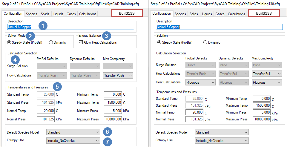
This section is normally only set up once when a project group is first started. The user will set the preferred operating mode, Steady State or Dynamic, temperature and pressure limits, etc.
The following can be configured by the user:
| Number | Setting/Selection | Description |
| Description | This is Optional. A description of the configuration file may be entered here. This should be kept short and meaningful as it is used in the Open Configuration Dialog box - xxxx.cfg(description). | |
| Solver Mode / Solution | The user must choose either Steady-State (ProBal) or Dynamic (may depend on license options). This selection can also be made on the first configuration page. Refer to Solver Modes for more information. | |
| Energy Balance Available from Build 139. |
The user must choose to either Allow Heat Calculations or not. This selection can also be made on the first configuration page. Refer to Energy Balance section below for more information. | |
| Calculation Selection | Refer to Calculation Selection section below for more information. | |
| Temperatures and Pressures | Refer to Temperatures and Pressures section below for more information. | |
| Default Species Model | The Species Model determines how the properties of streams containing a mixture of chemical compounds are calculated.
| |
| Entropy Use |
Entropy is only used in specific models such as FEM and other Thermodynamic Calculation Engine (TCE) add-ons.
|
Energy Balance
Available from Build 139. For Build 138 or earlier, please refer to Heat Calculations in the Calculation Selection.
The Allow Heat Calculations option determines whether an energy balance will be allowed to be calculated in any projects using this configuration file. Note: The user must have the Energy Balance license add-on for heat calculations to be performed in a project.
For users wanting a mass balance only, this option can be disabled to provide a faster calculation speed. However, do take note that this would result in all streams being at 25°C.
If energy balances will be required to be performed in projects, then this option must be enabled.
Note: The user may still change the options in the project (see Project Settings - Modes Tab), as this setting will set the maximum complexity allowed when using this configuration.
For example, the user may enable Allow Heat Calculations. All projects using this configuration file will start by default with energy balance calculations enabled, but the user may still change the individual project setting to disable energy balance calculations. However, if the user disables Allow Heat Calculations in the Project Configuration, then the user would not be able to change the Heat Calculations for any project from Off.
Calculation Selection
The user may select the default calculation options for projects using this configuration file. These are described below:
| Surge Solution | This determines the default method used in surge units in a dynamic project. (This is not applicable for ProBal) The three options available to the user in Dynamic mode are described here:
|
| Flow Calculations | This determines the default method used to solve the links, or pipes, in a dynamic project. (This is not applicable for ProBal) The two options available to the user in Dynamic mode are described below:
|
| Heat Calculations | Only available in Build 138 or earlier. For Build 139 or later, please refer to Energy Balance.
This determines the default method used to calculate the energy balance. The three options available to the user for both ProBal and Dynamic modes are described here:
|
Note: The user may still change the options in the project (see Project Settings - Modes Tab) or in individual units within a project (see Settings and Options on the Info Tab), as these settings are for the default behaviour when a project is created using this configuration file. The Max Complexity will set the maximum complexity allowed when using this configuration.
For example, the user may set the default heat calculation to None and the Max Complexity to Rigorous. All projects using this configuration file will start by default with no energy calculations, but the user may still change the individual project setting to have Rigorous heat calculations. However, if the user also set the Max Complexity to None then the user would not be able to change the Heat Calculations for any project from None.
Temperatures and Pressures
| Standard Temperature and Pressure |
|
| Normal Temperature and Pressure |
|
| Minimum and Maximum Temperatures and Pressures |
For example, if the user will be developing a smelter project, the maximum temperature may be 2500°C. However, if the user is developing a plant that uses ammonia, the Minimum temperature may need to be as low as -33°C. |
Note: The temperature limits defined above limit the temperatures in SysCAD models. The temperature of a feeder can not be set outside these limits. The temperature in a pipe may drift outside these limits but on the next mixture of feeds (e.g. feed to a unit), the temperature will be set to no less than 10 degrees below the minimum temperature and no more than 10 degrees above the maximum temperature. These limits will also be applied in a reaction block.
