Navigation: User Guide ➔ Menu Commands ➔ Edit ➔ Project Settings
This page is for Build 137 or later. For earlier builds, please see Project Settings 9.3
Command Path |
Edit - Project Settings
|
This command will open the Project Settings dialog box.
NOTE: SysCAD must be stopped for this command to be accessed.
The Project settings has five Tab pages:
Modes Tab
Build 139 or later |
Build 138 or earlier
|
 |
|
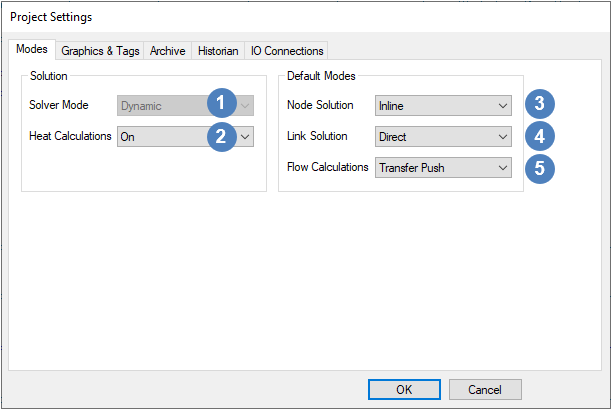
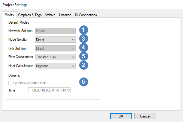
 Solver Mode / Network Solution
|
|
(left image) Heat Calculations (Build 139 or later)
|
This determines the method used to calculate the energy balance in the whole project. The two options available to the user for both ProBal and Dynamic modes, as shown in the above image, are described here:
- Off - For user wanting a mass balance only, using this option provides a faster calculation speed. However, do take note that this would result in all streams being at 25°C.
- On - Only available if Allow Heat Calculations has been enabled in the Project Configuration. SysCAD will perform an energy balance for the project. Note: The user must have the Energy Balance license add-on for heat calculations to be performed in a project.
|
(right image) Heat Calculations (Build 138 or earlier)
|
This determines the default method used to calculate the energy balance. The three options available to the user for both ProBal and Dynamic modes, as shown in the above image, are described here:
- None - For user wanting a mass balance only, using this option provides a faster calculation speed. However, do take note that this would result in all streams being at 25°C.
- Reduced - Only available if Max Complexity in the Project Configuration is set to Reduced or Rigorous. SysCAD will perform an energy balance for the project (the Reduced and Rigorous options are identical).
- Rigorous - Only available if Max Complexity in the Project Configuration is set to Rigorous. SysCAD will perform an energy balance for the project (the Reduced and Rigorous options are identical).
|
 Node solution
|
- This field is used in the Dynamic mode. It allows the user to set the default solution for surge units.
- The solutions that are visible in this field will be determined by the level selected for Surge Solution in the Project Configuration. Therefore, not all of the solutions shown below may be visible.
- All of the available solutions are:
- Inline - The units have surge and allow the user to implement internal level control in the unit.
- Direct - The units will have no surge and will behave in exactly the same fashion as a ProBal model.
|
 Link solution
|
This solution is Direct and may not be changed.
|
 Flow Calculations
|
- This field is used in the Dynamic mode. It allows the user to set the default calculation method for links, or pipes.
- The solutions that are visible in this field will be determined by the level selected in the Project Configuration. Therefore, not all of the solutions shown below may be visible.
- All of the available solutions are:
- Transfer Push - See Dynamic Transfer - Transfer Push Mode for more information.
- Transfer Pull - See Dynamic Transfer - Transfer Pull Mode for more information.
- Simple - The flow is calculated based on a relative pressure network, used when absolute pressure values are not available.
- Linear - The flow calculation is linear.
|
 Dynamic (Build 138 or earlier)
|
These two options are only available in Dynamic mode.
- The user may enable Synchronise with Clock by checking the tickbox.
- This will run the simulation in real time.
- A real time project uses the computer's clock as its time base, and is used in the historian and the trend windows.
- The Time input box allows the user to specify a current time. The format is: date <in number format>:time<hour:min.sec>.
|
Graphics and Tags
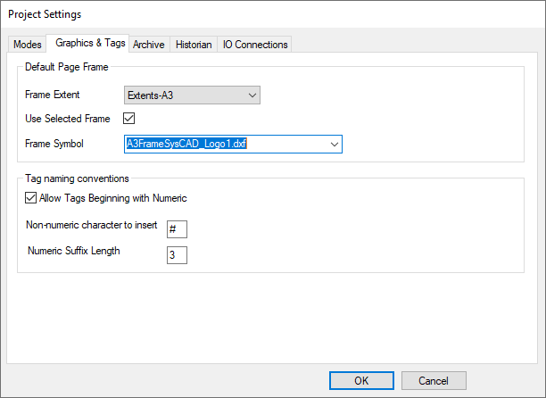
These are the defaults and rules are used when working with graphics and units.
Graphics Default
|
- Library - The location of the library containing any groups that the user may create or insert in the project. Please see Insert Group and Create Group.
- Group - The default here is Frames
- Page Frame - This sets the size of the markers on the graphics windows. The default is Extents-A3 (420 x 297 mm). NOTE: if user wishes to add in their own border then it is best to select the "none" option.
|
Tag Naming Conventions
|
- Allow Tags Beginning with Numeric - if this tickbox is enabled, then SysCAD will allow units and pipes to have tags beginning with a number. However, the tag MUST also contain at least one letter from the alphabet.
- Non-numeric character to insert - If the above tickbox is disabled, then SysCAD will insert this letter before a number in the case where the tag only contains numbers.
- Numeric Suffix Length - the numeric length used for default tags. The default is 3 - so for example pipes will be named P_001, P_002, etc.
|
IO Connections
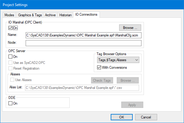
The user may set the rules for connecting to other software.
IO Marshal
|
- Enable the IO Marshal by checking the On tickbox.
- Browse for the marshal configuration file (.scm). If Marshal is running on a different PC (node) you will need to specify the node of the other location.
- SysCAD will open SysCAD Marshal and load in the IO tag data defined and report any errors. Any errors will be reported in the SysCAD Marshal program.
(Please also see SysCAD Marshal for more information on this topic)
|
OPC Server
|
- Enable the OPC Server by checking the On tickbox.
- Use as SysCAD2OPC - This allows you to run 2 copies of SysCAD both acting as differently named OPC servers. If this is disabled the normal name is SysCAD.OPC.
- Reset Registration - this registers the OPC server at startup.
- Use Aliases - Only available in SysCAD 9.3. Allows user to specify a list of tag aliases in a csv file. Use Browse to browse for the csv file. File is automatically reloaded after a change. Press Check Tags to check that tags in list are valid.
- Tag Browser Options - Only available in SysCAD 9.3. User can choose combinations of Tags (PlantModel, GlobalArea and any inserted unit models), $Tags ($Ctrl, $Pwr, $SDB and $Solver) and Aliases from dropdown list. This affects what items are displayed in the Browse window in the OPC Client. User can choose to have tags with or without conversions.
|
Alias File
|
Alias file contains two columns: First column is the alias used in the OPC Client, second column is the SysCAD tag. First row of text (or csv) file is ignored. The Alias must be unique (duplicates not allowed).
- Two types of Aliases can be used:
- A full SysCAD tag can be mapped to a full Alias. Tag can optionally contain conversions.
- A partial SysCAD tag ending with .* wildcard can mapped to an Alias. See example below.
|
DDE
|
The user may enable a DDE link by checking the On tickbox. (Please also see DDE for more information on this topic)
|
Alias example:
Alias |
Tag |
Description
|
Lvl |
TNK_001.Lvl
|
Lvl_Perc |
TNK_001.Lvl (%)
|
Pipe5 |
P_005.Qo.*
|
In this example, all P_005.Qo part tags will be available in the OPC Client as Pipe5. For example, using Pipe5.Qm (t/h) in OPC Client will map to P_005.Qo.Qm (t/h).
(Please also see OPC Server for more information on this topic)