Navigation: User Guide ➔ Menu Commands ➔ Solver Setup (Dynamic)
Related Links: Solver Set up for Steady State Projects
| Command Button |

|
| Command Path |
Edit - Solver Setup
|
NOTES:
- This command will display the following for a Dynamic project.
- SysCAD must be stopped for this command to be accessed.
This command will allow the user to change the dynamic simulation options, such as solving method, step sizes and so on prior to running the SysCAD dynamic simulation. These are done through the Dynamic dialog box. When the settings have been changed, press the OK button to save the new settings and close the dialog box.
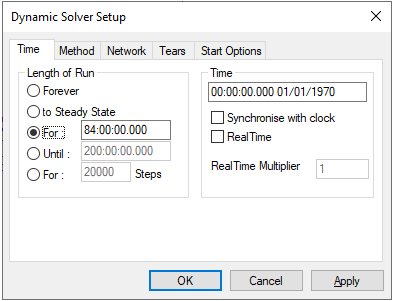
Time
|
A number of options are available for controlling how long a dynamic simulation must run or solve for:
- 'Forever' where the solver never stops
- 'To Steady State' where solver runs until it detects there are no more changes in the process variables. This mode requires configuration of criteria in the Solver Setting - SS Monitor Tab.
- 'For' a specified time span
- 'Until' a specified end time
- 'For X Steps' runs for a specified number of steps
The current simulation date and time can be specified, unless "synchronise with clock" is selected, in which case the simulation date and time is the current real date and time.
There are three ways a dynamic model can run in terms of time management:
- As fast as possible: "Synchronise with clock" and "RealTime" must not be selected. SysCAD will start each time step immediately after the current time step is complete. The speed of the simulation will depend on computer processing power as well as size and complexity of the model.
- Real Time: "Synchronise with clock" and "RealTime" are both selected. "RealTime Multiplier" is 1. The purpose of this mode is to run in real-time synchronised with your PC date and time. After a time step is completed, SysCAD solver will idle until the progress of real-time is the same as the step size, at which time the next time step will start. This option is typically used for control system testing and operator training. It is important that the computers actual solver time for a step is less than the selected time step.
- Accelerated Time: "Synchronise with clock" is NOT selected and "RealTime" is selected. The user can specify a "RealTime Multiplier", for example, if this is 2 SysCAD will run twice as fast as real time. This selection gives a consistent progress of time steps and as described for the above Real-Time option, SysCAD will idle at the end of a time step to maintain the required multiplier. Again, care should be taken in selecting a suitable time step so that the desired real-time multiplier can be achieved for a given project and PC.
|
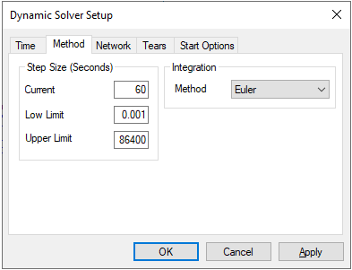
Method
|
SysCAD solves the dynamics of a flowsheet in incremental time steps called Step Size. The step size determines how long a time period is being simulated for when the flowsheet is being solved. A single step can have multiple iterations to solve the flowsheet and associated controls, similar to solving a steady state project. The maximum number of iterations per step is set on the Tears tab. Updates of number displays in trend windows and so on can be refreshed (or stored in historian) at the end of a step.
The method used for the dynamic simulation can be changed here. The methods available are Euler, Runge-Kutta2, and Runge-Kutta4.
|
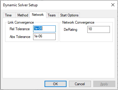
Network
|
This tab page contains the solution network settings. These can be used to improve the SysCAD speed in obtaining a solution.
Link Convergence
- Rel Tolerance - The relative tolerance required for the solution. If this value is increased, then the model will solve faster, but will be less accurate.
- Abs Tolerance - The absolute tolerance required for the solution. If this value is increased, then the model will solve faster, but will be less accurate.
Network Convergence
The DeRating parameter is used for convergence of the network.
|
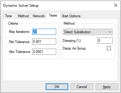
Tears
|
- A tear is required to solve models that contain one or more recycle streams.
- SysCAD determines the optimum position for the tears using a modified version of the algorithm described in the following paper:
- Ollero P. and Amselem C., "Decomposition Algorithm for Chemical Process Simulation", Chem. Eng. Res. Des., 61, 303, (Sept. 1983)
- SysCAD determines the position of the tears as part of the startup sequence each time the model is solved. It is possible that tears become temporarily "inactive" during the running of a dynamic model because of, by example, the closing of valves.
- Ideally a tear (recycle) needs to be converged each time step. If tear is not converged within specified maximum iterations than the error is remembered and used as a correction in following time steps.
- All these settings can also be changed on the GlobalTear Access window page for $Solver. These global settings can be overwritten for individual tears.
Criteria
- Max Iterations - The maximum number of iterations that SysCAD will perform in each time step in order to iteratively solve recycles (i.e. converge tears).
- Rel Tolerance - The relative tolerance used in recycle tears.
- Abs Tolerance - The absolute tolerance used in recycle tears.
Method
The user may choose from different methods for solving Tears. See Convergence Methods for a description of these different methods, Damp as Group and the Damping Factor.
|
Start Options
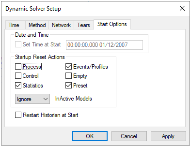
|
Date and Time:
The user may enable Set Time at Start and then set the starting time for the simulation.
Startup Reset Actions:
| Process |
This will empty all pipes and flow values when the run begins. Default is off.
|
| Control |
This will reset all controllers back to 'Base' state, i.e. the same state as when the controller is first inserted into the project. This is mainly relevant for PID controllers. Default is off.
|
| Statistics |
Selecting this will Reset the Statistical blocks when scenario is started. Default is on.
|
| Events/Profiles |
This will reset all Event and Profiles back to start time. Default is on.
|
| Empty |
This Empties all containers with surge, e.g. Tanks. Default is off.
|
| Preset |
This resets all tanks that have the 'Preset.On' button ticked and have Preset data. Default is off.
|
Please also see Solver Actions in the Solver Setting access window and Actions Commands for more information.
Historian:
- Restart Historian at Start: This option clears any old data in the historian at the start of the simulation.
|


