Convergence Methods
Navigation: User Guide ➔ Solver ➔ Convergence Methods
| Project, Model and Solver Settings | Simulation Modes and Solver Setup | Solver Methodology, Convergence and Tolerance | Solving Models | ||||||||||||
|---|---|---|---|---|---|---|---|---|---|---|---|---|---|---|---|
| Project Settings | Solver Settings | Plant Model | Constants | Simulation Modes | ProBal Setup | Dynamic Setup | Solver Status | Solver Methodology | Convergence Methods | Tolerance Testing | Evaluating Sub-Models | Flash Train | Mass & Energy Balance | Referenced Variables | Demand |
Related Links: Tear, Solver Setting - Tears, Solver Setting - GlobalTear
Introduction
The SysCAD solver uses a "sequential modular approach" rather than an "equation-based approach" for solving networks as represented by flowsheets. An iterative sequential tear stream solver method is used in SysCAD with some advantageous adaptations specific to our target customers and industries.
The SysCAD solver, at startup, uses an algorithm to identify recycles and determine minimum Tears in streams. SysCAD builds Tear Blocks for these. The concept of tearing has evolved together with modular flowsheeting approaches for steady state simulation to solve material and energy balances. Tearing involves decoupling the interconnections between the modules (equipment unit models, pipes, etc.) so that sequential information flow takes place. Tearing is required because of loops of information (species masses, energy, pressure, etc.) created by recycle streams. In addition to recycle streams of material flows it is possible to have tears for other types of circular data paths (e.g. controllers) that are part of the criteria for convergence. In tearing in the iterative solver you start with providing the "output side" of the tear initial values (zeros, previous results or guesses) for the unknowns (the tear variables). Then calculate the values on the other side of the tear from the sequential evaluation of the modules (unit models, etc.). Then these values or used, based on a selected algorithm (with various damping methods, etc.), to determine the next estimate for use in these values to solve the next iteration. This is repeated until each tear variable is converged to a specified tear tolerance.
The convergence of these tear blocks can be resolved by using one of the following methods:
- Direct Substitution
- Adaptive Direct Substitution
These methods are selected in:
- Solver Setup dialog box
- Solver Settings - GlobalTear access window
- Solver Settings - Tears access window
A range of other information about the solver can also be viewed from the Access Windows: Solver Settings
Overview
A simple model, with no recycle loops can be solved directly. We know all the inputs, so we can evaluate all the model units connected to these inputs. This gives us a fixed set of outputs which may feed to subsequent (downstream) units, and we can then evaluate these as well. We continue all the way through the network, being able to solve at each state.
The problem of course arises if there are recycle streams in there, given that we don't know the contents of the recycle stream until we have solved all the units and pipes before that.
Any complex model can be divided into a number of submodels that can be solved directly by starting with the flows at the various inputs and sequentially solving all the units connected to these inputs. This subdivision is made at flanges called tears, and streams associated with such a flange are tear streams.
In the various SysCAD solution methods, the solver is attempting to converge the model by adjusting the values it passes across the tear until it sees the same values coming back at the next step.
A Simple Example
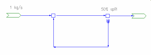
This is the simplest possible model having a recycle stream.
We split off some fraction (here 50%) of the flow at the second tie, and feed it back to the first tie. So we don't actually know the flow into the first tie until we have found the flow going to the second tie, but that depends on the flow from the first tie. In this case we can trivially determine that we should have 2kg/s flow between the ties, sending back 1kg/s to make up the total when added to the incoming flow.
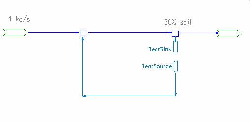
In solving this problem, SysCAD first does some network analysis and figures out how to add tear streams to divide the problem into a number of problems that can be solved individually:
The tears are indicated in SysCAD by the double chevron symbol ">> >>" and you can think of this as replacing the tear by a source and a sink. In this example, SysCAD has located the tear in the recycle stream (or more correctly, at the join (flange) between the second tie and the pipe:
Now if we know the flow in the feeder TearSource we can determine the flows in the rest of the network. Since we don't know this directly, we proceed iteratively, transferring data (flows, temperatures and other properties) from TearSink to TearSource at each step and determine a new value at the sink. Hopefully, after some number of steps, things will reach a point where transferring the sink value will lead to an identical (within tolerance) value at the source.
Let us look at how this works for this simple problem. At the first step we have no flow at the tear source, so the tear stream is empty. So we have just the 1kg/s flow at the second tie, and this splits 50/50, giving 0.5kg/s at the tear sink.
At the next step, we put the 0.5kg/s from the sink into the source. The first tie is now getting 1.5kg/s - 1kg/s from the feed and 0.5kg/s from the recycle tear stream. So the second tie gets 1.5kg/s as well, of which 0.75kg/s end up in the tear sink. At the third step we have .875kg/s there, at the fourth step 0.9325kg/s and so on. After about 20 or so steps things settle down and we have 1kg/s in the recycle loop, and the problem has converged.
   Recycle      Between Ties
1  0            1.0
2  0.5          1.5
3  0.75         1.75
4  0.875        1.875
5  0.9325       1.9325
....
18 0.99999905   2
Direct Substitution Method
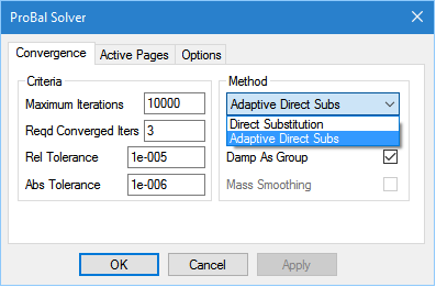
SysCAD has an implementation of the method described above for its solver and you can see it in the Solver Setup) dialog box.
With direct substitution, the convergence procedure is very simple, we just transfer the values across the tear at each stage. If the problem is well-behaved, then it will eventually converge. However there are two potential pitfalls
- If we transfer the entire flow across, we might end up with instability. This is the case especially if we have controllers present - sudden changes in flow can make them become unstable as well, and this feeds back to the tear algorithm.
- If things are changing slowly, then it will take quite a number of steps to asymptotically approach the correct solution.
The first situation can be dealt with by using damping, and we can even do this in Direct Substitution. At any step we look at the change across the tear and only apply some part of that change. However the second option in the Solver Setup Dialog implements this in a semiautomatic manner (and is the default ProBal solver method)
The second situation can be improved by using an acceleration technique, where the solver 'sees' that we are moving slowly in a particular direction and attempts to 'jump ahead' to a better solution.
Understanding when to use these methods and how to tune them for optimum performance is the key to rapid and stable solution of large problems.
Applying damping doesn't help with this simple example at all. If we have 50% damping then at the first step, instead of setting the flow at the tear source to 0.5kg/s, we set it to just 0.25kg/s. At the next step we only have a flow of 1.25kg/s between the ties rather than the 1.5kgs we had without damping. The recycle flow builds up much more slowly and it takes twice as long for the model to converge:
    Recycle   Between Ties
1   0         1
2   0.25      1.25
3   0.4375    1.4375
4   0.578125  1.578125
5   0.683593  1.683593
6   0.762695  1.762695
7   0.822021  1.822021
8   0.866516  1.866516
9   0.899887  1.899887
  ...
37  0.999968  1.999968
38  0.999976  1.999976
The need for damping
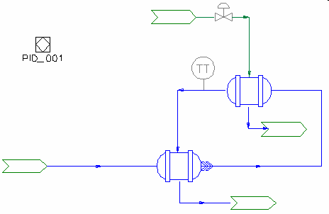
To understand where damping helps let us look at a simple model with a recycle loop and a controller.
The idea is to adjust the steam flow to the live steam heater to achieve a given setpoint on the outlet. If the temperature is too low, the valve will open and admit more steam; if it is too high the valve will close.
In this case the recycle comes from heat being transferred through the recuperation heat exchanger. This is a simple but realistic example of interaction between the controller and the recycle tear. Now if the gain of the heater controller is set too high, we can overshoot on the steam supply
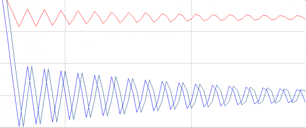
The red line here represents the desired steam temperature, while the blue and green lines are the temperatures across the tear stream. The blue line is the temperature into the tear, while the green line is the temperature out. We are using Direct Substitution, so the green line is just the blue line shifted by one step.
Observe what is happening here. When the temperature out of the tear is raised, the controller doesn't respond fast enough to shut off the steam. The temperature out of the live steam heater continues to rise above the setpoint, with this feeding through the tear and we get a typical controller induced oscillation. It converges, but slowly.
Now this could be fixed by reducing the gain on the controller, but the real issue is the response at the tear. Instead of just blindly passing on the incoming value, the tear should pass on a value in-between the old value and the new value, in other words not making such a drastic change.
Instead of setting the new outgoing value to the new incoming value, we make it some combination of the new value and the previous outgoing value:
[math]\displaystyle{ T_o = (1-\alpha) T_i + \alpha T_o' }[/math]
where [math]\displaystyle{ T_o' }[/math] is the previous output value and [math]\displaystyle{ \alpha }[/math] is the damping factor.
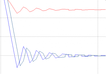
Apply a small amount of damping (20%) and you can see that the solution converges much more rapidly: the changes to the tear output value (green trace) are in synch with the changes in the input, but reduced in magnitude by the amount of damping.
With 50% damping, the solution converges pretty much instantly.
Of course you don't want to have to go around figuring out how best to set the damping for any given scenario, and fortunately SysCAD can actually do this for you, using the Adaptive Direct Substitution method.
Adaptive Direct Substitution Method
In the first simple example, damping was completely useless and we should turn it off. In the second case, we needed damping to get the solution to converge. Adaptive Direct Substitution (ADS) lets SysCAD make this decision; it looks at how the solution is converging and adjusts the damping accordingly. If things are ticking along nicely and moving steadily towards a solution, it reduces the damping. If things start getting out of control and swinging back and forth, then the damping is increased. In the first example, it will set the damping to zero. In the second case it will increase the damping as much as is needed to get things to work properly.
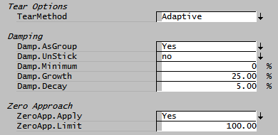
We have two parameters that control this tendency: Damp.Growth and Damp.Decay. These parameters can be changed on the Solver Settings - GlobalTear
In general we want to increase the damping rapidly as soon as things start getting out of control, while dropping it slowly as we approach a solution so as not to upset things too much. So the DampingGrowth parameter is usually larger than the DampingDecay factor. And you probably don't need to tamper with these parameters at this stage. (The MinDampingReqd parameter also appears on the ProBal Setup... dialog; in the case of ADS it prevents the damping from dropping below this value)
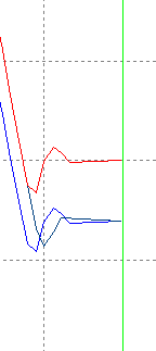
Now look at what happens: the solution converges right away; the damping is being set to an optimal value.
Unsticking the solution
There are some cases where it is important not to have too much damping in the tear stream, because we want the changes to follow the input reasonably quickly.
For example, in a model where there are PID controllers combined with tear streams, there are often slow changes in the values for the PID variables to assure controller stability. However if the value at a tear is heavily damped, the controller may overcompensate because it takes a large number of iterations to see the required change. Or if we put in a step change to some process parameter, we generally want the various influenced values to move rapidly in the right direction before we are in a position to actually converge.
Under some circumstances, the ADS algorithm can be fooled into thinking that the solution needs to be heavily damped, whereas we actually need to reduce damping. In particular if the solution is trending monotonically in one direction for a number of steps, then we generally need to reduce the damping.
The solver can now recognize this situation and reduce damping in the case of monotonic trends. This may not be desirable behaviour in all cases so that the unstick option is available on a tear by tear basis.
Zero Approach
As the tear block approaches zero flow, the adaptive method can be switched off to use the direct method.
The zero approach will apply only to species mass flows for a Pipe Tear (i.e. not relevant for pressure, temperature and quality tear variables).
ZeroApp.Measure (in terms of Tol.Abs (kg/s)) = Measval / AbsTol for any variable in a block
ZeroApp.Measure displayed for a TearBlock is the maximum of the variables in a block.
If the largest ZeroApp.Measure for a Tear is < 1.0 and WorstError < ZeroApp.Limit then the tear is advanced using direct substitution instead of adaptive.
Group Damping
The default (Global) setting for Build 136 and earlier is to group-damp all tears - i.e. all the tear variables are damped using the same damping factor. For small models (and new users) this is a satisfactory approach, however it can cause slow convergence issues with large plant models. If a model converges slowly (but steadily), especially when a change is made to a key flow parameter, check the Solver Convergence window:
- If a number of flow parameters have high damping, uncheck Damp as Group in the Solver Setup dialog or change the setting to 'No' on the GlobalTear Access window page for $Solver.
- It is also possible to disable group damping for an individual tear only - if unchecking Damp as Group causes stability problems, recheck it and remove group damping for the tear (in this case Flng_053) identified as slowing the overall convergence as shown in the next section.
Modifying Convergence methods for individual tears
Finally note that it is possible to "mix and match" and use different methods on different tears. If the complex network above were a part of a larger model, we could specify Direct for this subnetwork alone.
A list of all the Tears, including summaries of settings and results, is available on the Tears Access window page for $Solver.
To access the individual tear information, open the Access window associated with the Tear for the pipe. The graphics symbol for access is the chevron on the pipe. Alternatively you can navigate to the Tear of interest from $Solver Tears page. You can then change the convergence method, settings and tolerances for the selected tear of interest.
