Falling Film Evaporator 4
Navigation: Models ➔ Energy Transfer Models ➔ Falling Film Evaporator 4
| Flash Tank | Evaporator | Falling Film Evaporator | Shell&Tube Heat Exchanger | Simple Heat Exchanger | Barometric Condenser | Direct Contact Heater | Simple Heater | Simple Evaporator | Simple Condenser |
|---|
General Description
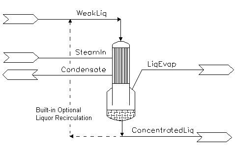
The falling film evaporator is used for liquor concentration. A schematic of the unit operation and its inlets and outlet are found in the diagram below.
In a falling film evaporator, weak liquor is pumped to the top of the unit and distributed to the tubes where it runs down as a film. Steam is entered on the shell side, the condensation of the steam provides energy to heat and if hot enough, evaporate water from the weak liquor, thus concentrating the liquor stream.
The concentrated liquor and Liquor Evap streams will leave the system at Saturated Pressure based on the Final liquor temperature.
On the shell side, a heat loss term can be specified. This accounts for any inefficiency of the unit. If this heat loss term is zero, then all the energy from steam condensation will be used to heat and evaporate the weak liquor. The condensate will leave the system at saturated temperature based on the steam pressure.
NOTES:
- To avoid any accidental incorrect feed liquor specifications, (thus left at default conditions of 20°C and atmospheric pressure), the model has a minimum pressure which the unit operation must keep to. This field is user configurable and can be used to prevent unrealistic answers from the model.
- The Falling Film Evaporation Project, which is distributed with SysCAD in the Examples folder, demonstrates the use of this model in a SysCAD project.
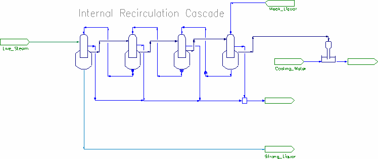
- This Falling Film Evaporator model can be included as part of a flash train or evaporator cascade. See examples below.
- A SysCAD model using the earlier FFE2 may be converted to the new model by using Change Unit. The connections are identical so the new model is a "drop in" replacement. Configuration is similar, but simpler when connected to other flash train components and no pressure control needs to be done.
Diagram
The diagram shows a drawing of the Falling Film Evaporator, with the required connecting streams. The Falling Film Evaporator expects 2 inlets: Steam In, and Weak Liquor in. Three outlets must also be connected, these are: condensate, concentrated liquor and evaporated vapour from the liquor.
Inputs and Outputs
| Label | Required Optional |
Input Output |
Number of Connections | Description | |
| Min | Max | ||||
| Tube_In | 1 Required | In | 1 | 10 | Weak Liquor |
| Tube_Out | Required | Out | 1 | 1 | Concentrated Liquor |
| Shell_In | 1 Required | In | 1 | 10 | Steam in |
| Shell_Out | Required | Out | 1 | 1 | Condensate out |
| Tube_Vap_Out | Required | Out | 1 | 1 | Evaporated Vapour |
| Shell_Vent | Optional | Out | 0 | 1 | Optional vent for non-condensables and excess steam. |
Behaviour when Model is OFF
If the user disables the unit, by un-ticking the On tick box, then the following actions occur:
- All streams connected to 'Tube In' will flow straight out of 'Tube Out' with no change in temperature and no evaporation.
- All streams connected to 'Shell In' will flow straight out of the 'Shell Out' with no change in temperature and no condensation.
So basically, the unit will be 'bypassed' without the user having to change any connections.
NOTE: If the FFE4 unit being switched off is part of an flash train, then the flash train may break as there will be NO flash vapour to supply the down stream unit. Please see Hints and Comments for more information.
Model Theory
The amount of evaporated steam from the liquor stream is calculated based on:
1) Energy from fully condensing of steam.
- [math]\displaystyle{ Q = m_{steam} \; \lambda_{steam} }[/math]
2) Less heat loss specified by the user
3) Less energy used to heat liquor stream to required temperature.
- [math]\displaystyle{ \int\limits_{T_1}^{T_2} \; m_{liquor} \; Cp \; dT }[/math]
4) Mass of evaporated steam is = Energy available / latent heat (Final Liquor T, P)
Operating Modes Discussion
The operating modes are similar to those in the existing Evaporator models.
Condensing Modes
- All
- All (Calc Demand)
- All (Demand Flashtrain)
- All (General Demand)
The first two of these operate with determined feed flows, the latter two control their feed flow through connection to a flash train or a feeder with Demand enabled.
In the All mode, all the condensable feed is actually condensed, for a given feed flow, this determines the heat to be transferred to the evaporator. The surface area required to transfer the heat load is displayed as a result.
For All (Calc Demand) the user is responsible for adjusting the feed flow to meet the required demand which is calculated and displayed. (This can be done using a SetTag controller or other logic)
If the supplied flow doesn't match the demand, then a warning is displayed.
For the other two options the feed should be connected to a source with demand enabled, or to a Flashtrain source such as a flash tank or the evaporator section of another FFE.
General Discussion
Falling film evaporators are a combination of flash tanks and heat exchangers so their operation has subtleties that combine issues associated with both. Unlike a normal heat exchanger, it is possible for the temperature in the liquor stream to rise or fall, depending on the evaporating pressure.
It is also possible for the unit to have condensing even if the actual feed liquor temperature is higher than the steam saturation temperature! This is because the final liquor temperature is determined by the tubeside operating pressure, and the temperature after flashing may be lower than the steam saturation temperature.
In such cases, recirculation is important to maintain a low tubeside temperature. Recirculation takes cold post flashed liquor from the outlet and mixes it with the incoming stream, reducing the effective tubeside temperature. (Recirculation is also important operationally, maintaining a high film coefficient and reducing scaling.)
A good understanding of the operating principles of evaporators is helpful in constructing and debugging models.
Evaporating Mode
- Standalone (Manual)
- Flash Train
In Standalone (Manual) operation, the user must specify the final liquor pressure (or atmospheric pressure) or temperature.
In Flashtrain mode, the vapour outlet must be connected to a Flashtrain sink such as a Barometric Condenser, Shell-Tube condenser or another FFE4 condenser.
Flowchart
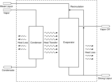
The model combines separate condenser and evaporator (flash tank) models that interact through heat transfer between them. An optional recirculation stream can take some fraction of the evaporator outlet and recycle to the inlet. Environmental heat losses can be specified for both the condenser section and the recirculation pipe.
Data Sections
The default access window consists of 5 sections,
- FFEvaporator4 tab contains general information relating to the unit.
- Results - This second tab contains unit results for the shell and tube side.
- VLE tab - Contains the VLE information for the tube side.
- VLESS tab - Contains the VLE information for the shell side.
- QLiqFeed - Optional tab, only visible if ShowQLiqFeed is enabled. This page shows the properties of the feed liquor stream to the Evaporator (not including recirculation nor steam feed).
- QTubeIn - Optional tab, only visible if ShowQTubeIn is enabled. This page shows the properties of the re-circulation stream from the Evaporator mixed with the fresh feed stream. This is the feed to the Tube side.
- Info tab - contains general settings for the unit and allows the user to include documentation about the unit and create Hyperlinks to external documents.
- Links tab, contains a summary table for all the input and output streams.
- Audit tab - contains summary information required for Mass and Energy balance. See Model Examples for enthalpy calculation Examples.
Falling Film Evaporator 4 Page
Unit Type: FFEvaporator4 - The first tab page in the access window will have this name.
| Tag (Long/Short) | Input/Calc/Options | Description |
| Tag | Display | This name tag may be modified with the change tag option. |
| Condition | Display | OK if no errors/warnings, otherwise lists errors/warnings. |
| ConditionCount | Display | The current number of errors/warnings. If condition is OK, returns 0. |
| GeneralDescription / GenDesc | Display | This is an automatically generated description for the unit. If the user has entered text in the 'EqpDesc' field on the Info tab (see below), this will be displayed here. If this field is blank, then SysCAD will display the UnitType or SubClass. |
Requirements | ||
| On | Tick box | If this option is switched off, then the unit operation will behave like a pipe model. Thus, inlet conditions = outlet conditions and no heat transfer will take place. |
| ShellToTubeVap_WhenOff / ShellToTubeVap | Tick Box | This is only visible when the unit is OFF. Allows the steam input to the condenser to be directed to Evaporator Flash Vapour Outlet. Thus steam/flash vapour in will bypass the unit and becomes feed steam to the downstream FFE4 unit. If this is not ticked, the Vapour in will be sent to the condensate line as without condensing. |
| Evaporator (Tube) Side Operation | ||
| EvapMode | Standalone (Manual) | In this case the user specifies the evaporating conditions (T or P). |
| Flash Train | The Evaporator will act as part of a Flash Train. In this mode the Evaporator vent must be connected to a steam consumer, such as a Barometric Condenser or the condenser section of other FFE4 models. The steam requirements of the steam consumer will drive the operating pressure of the Evaporator, therefore the user may NOT set the operating temperature or pressure. | |
| OperatingP
The user may only set the operating pressure or temperature of the Evaporator if it is using the Standalone EvapMode. | ||
| Method | Atmospheric | All flash calculations will be done at Atmospheric Pressure. The atmospheric pressure is calculated by SysCAD based on the user defined elevation (default elevation is at sea level = 101.325 kPa). The elevation can be changed on the Environment Tab page of the Plant Model. |
| RequiredP | All flash calculations will be done at the user specified pressure. | |
| RequiredT | All flash calculations will be done at the user specified temperature. | |
| PressureReqd / P_Reqd | Input | The Required Flash Pressure - This is only visible if the RequiredP Method is selected. |
| TemperatureReqd / T_Reqd | Input | The Required Flash Temperature - This is only visible if the RequiredT Method is selected. |
| Result | Display | This field displays the operating pressure of the Evaporator. |
| MinFlashP | Input | The minimum Pressure at which the Evaporator may operate. This is visible if the Evaporator is configured as part of a Flash Train, as it will not allow the unit to drop to an unrealistic pressure. It is recommended to use a realistic minimum pressure for the evaporator, for example, for stage 1 where temperature is higher, the minFlashP maybe set to 100 kPa absolute if the Evaporator is to be operated above atmospheric; whereas for the last stage where temperature is low, the minFlashP maybe set to a small number if it is expected to be under low vacuum. It is not recommended to set the MinFlashP to zero kPa absolute, it should be at least a small number. |
| Condenser (Shell) Side Operation | ||
| CondensingMode | All | All vapour is condensed and the required surface area is displayed |
| All (calc demand) | All vapour is condensed and a warning is displayed if the calculated demand is different to the feed rate | |
| All-Demand Flashtrain | The feed is connected to a Flash Train source such as a flash tank or another FFE4 unit. | |
| All-Demand General | The feed is connected to a Feeder with Demand.On enabled. | |
| SetPressure | Tick box | Only visible with the All (General Demand) CondensingMode. This enables the user to set the condenser (shell) pressure and models a pressure control valve on the inlet. |
| Shell.PressureReqd / Shell.P_Reqd | Input | Only visible with SetPressure selected. Steam inlet pressure is adjusted to the set shell side pressure. This will affect the condensate outlet temperature and heat exchange with the tube side. Can be used to control the outlet Temperature for the FFE. NB this pressure must be equal to or less than the steam supply pressure. Pressure change is adiabatic, isenthalpic process. |
| Heat Exchanger Details | ||
| HTC | Input | The user specified heat transfer coefficient. |
| Area | Input | The user specified heat transfer area. |
| LMTDCorrection | Input | User specified correction factor for LMTD, useful for when liquor is subcooled. [math]\displaystyle{ Q = UA \times \hbox{LMTD} \times \hbox{LMTD}_{Correction} }[/math]. |
| DemandFlow.ReportRelTol | Input | Only visible with the All (General Demand) Method. The required tolerance for error condition messages for demand calculations. The actual tolerance is reports in the DemandFlow.RelErr field. |
| Recirculation of Liquor | ||
| Recirc... | ||
| On | Tick Box | This enables the recirculation option. |
| Fraction | Input | Only visible if the Recirc option has been selected. The user specified recirculation fraction. The recirculation fraction = Recirculation Flow/(Liquor Product + Recirculation Flow) |
| TemperatureIn / Ti | Result | The temperature of the liquor feed after mixing the actual feed with the recirculation stream. |
| MassFlow / Qm | Result | Mass Flow of the liquor feed after mixing the actual feed with the recirculation stream. |
| VolFlow / Qv | Result | Volume Flow of the liquor feed after mixing the actual feed with the recirculation stream. |
| Acceleration | Tick Box | If this is ticked, the Wegstein Acceleration method will be used as the internal convergence algorithm for calculating re-circulation. |
| Environmental Heat Loss (Recirculation) | ||
| ThermalLoss.Method | None | No Heat loss in the recirculation pipework. |
| Fixed Loss | Heat loss in the recirculation pipework specified as a fixed heat flow. | |
| DeltaT | Heat loss in the recirculation pipework specified as a temperature drop. | |
| ThermalLoss.Reqd | Input | Visible with the Fixed Loss method. User specified Heat loss Required. |
| ThermalLoss.DeltaT | Input | Visible with the DeltaT method. User specified Temperature Drop. |
| ThermalLoss.Loss | Result | Actual Heat Loss due to recirculation. The heat loss will reduce the temperature of the Tube In stream (Recirculation + Fresh Feed). |
| Environmental Heat Loss (ex Shell Side) | ||
| Shell.ThermalLoss.Method | None | No Heat loss in the condenser section. |
| FixedLoss | Heat loss in the condenser specified as a fixed heat flow. | |
| Ambient | Heat loss is expressed as Energy/degree of temperature difference to ambient. | |
| Shell.ThermalLoss.Reqd | Input | Visible with the Fixed Loss method. User specified Heat loss Required. |
| Shell.ThermalLoss.Ambient | Input | Visible with the Ambient method. User specified Energy/degree of temperature difference to ambient. |
| Shell.ThermalLoss.Loss | Result | Actual Heat Loss in the steam condensing section. The heat loss will reduce the amount of energy available for exchange with the tube side (for heating and evaporation). |
| User Set Limit Warnings | ||
| TubeSideDeltaT | Tick Box | This enables the tube side change in temperature warning. |
| MaxTubeSide_dT | Input | Only visible if TubeSideDeltaT is selected. The user specified maximum tube side change in temperature before a warning is generated. |
| SpecificVapLoad | Tick Box | This enables the specific vapour load warning. |
| MaxVapPerArea | Input | Only visible if SpecificVaporLoad is selected. The user specified maximum specific vapour load (flow of vapour per unit area) before a warning is generated. |
| Show Tube Side Flows | ||
| ShowQLiqFeed | Tick Box | QLiqFeed and associated tab pages (e.g. Qm) will become visible, showing the properties of the combined fresh liquor feed stream. See Material Flow Section. |
| ShowQTubeIn | Tick Box | Only visible if the Recirc option has been selected. QTubeIn and associated tab pages (e.g. Qm) will become visible, showing the properties of the combined liquor feed stream including the recirculation stream. This is the sum of the LiqFeed and Recirc streams. See Material Flow Section. |
| Connection Checks | ||
| Tube.FlashOK | Feedback | 1=True, 0=False. Checks if the tube side (Evaporator) flash vapour stream is connected to other flash train enabled stream. |
| Shell.FlashOK | Feedback | 1=True, 0=False. Checks if the shell side vapour input stream is connected to other flash train enabled stream, e.g. other FFE4 Vapour Out stream. This is normally 0 for the lead FFE4 units, but should be 1 for subsequent FFE4 units in the circuit. |
| Shell.DemandOK | Feedback | 1=True, 0=False. Checks if the shell side vapour input stream is connected to demand enabled feed streams, e.g. feeder with demand on. This is normally 1 for the lead FFE4 units, but should be 0 for subsequent FFE4 units in the circuit. |
Results Page
The page contains the results fields.
| Tag (Long/Short) | Calc | Description |
Results | ||
| U*A | Calc | heat exchanger UA. |
| Duty | Calc | The duty of the falling film evaporator heat exchanger. The equation for this is: Q = UA * LMTD |
| HXDuty | Calc | The duty available from condensing the steam. |
| TheoreticalArea / TheorArea | Calc | The calculated area required to perform the heat exchanger duty. |
| SpecVapLoad | Calc | The specific vapour load. (Calculated using Shell.CondMassFlow / Heater Area). |
| LMTD | Calc | heat exchanger log mean temperature difference |
| TemperatureCrossover | Feedback | 1=True, 0=False. Indicates if temperature cross occurs, see Hints - Recirculation for more information. |
| TemperatureHigh | Feedback | 1=True, 0=False. Indicates if the feed temperature is higher than the condensing temperature. see Hints - Recirculation for more information. |
| HeatFlow | Calc | Displays the total heat loss in the model, includes environment heat loss due to recirculation and environment heat loss in the shell side. |
| Calculated Vapour Flow Demand | ||
| DemandFlow.Reqd | Calc | The calculated steam flow to meet the Heater requirements. When the heater is not in GeneralDemand or FlashTrain mode, use a General controller or SetTag Controller to get this value to set the steam flowrate. |
| DemandFlow.Actual | Calc | The actual steam flow to heater. |
| DemandFlow.Error | Calc | The error between the demand flow and actual flow. This will warn the user if the amount of steam supplied does not match the heater requirements. Most common when the heater is not in demand mode and the steam flow has not been set up to auto adjust. |
| DemandFlow.RelError | Calc | The relative error between the demand flow and actual flow. User can set the error limit for error reporting in the DemandFlow.ReportRelTol field. |
| Shell Side (Condensing) | ||
| Shell.TemperatureIn / Shell.Ti | Calc | Temperature of the stream entering the Shell side. |
| Shell.TemperatureOut / Shell.To | Calc | Temperature of the stream leaving the Shell side. |
| Shell.SaturationT / Shell.SatT | Calc | Shell side Saturation temperature. |
| Shell.PressureIn / Shell.Pi | Calc | Shell inlet pressure. |
| Shell.PressureOut / Shell.Po | Calc | Shell outlet pressure. |
| Shell.MassFlow / Shell.Qm | Calc | The mass flowrate going through the Shell side. Includes any non-condensables or liquid present (2 phase flow). |
| Shell.CondMassFlow / Shell.CondQm | Calc | The mass of condensing vapour going through the Shell side. Excludes any non-condensables or liquid present (2 phase flow). |
| Shell.DmdQm | Calc | The mass flow going through the shell side from demand calculation, e.g. from feeder with Demand.ON or other flash train units. |
| Shell.FxdQm | Calc | The mass flow going through the shell side from other side streams, e.g. from feeder with user specified flowrate (fixed amount). |
| Tube Side | ||
| Tube.TemperatureIn / Tube.Ti | Calc | Temperature of the "fresh feed" entering the Evaporator section, i.e. excluding re-circulation. Please Note that the LMTD calculation uses "Tube + Recirculation" T, to see this value, please tick the FFEEvaporator4 Tab - Show Tube Side Flows section - ShowQTubeIn tick box, then go to the QTubeIn Tab for information. |
| Tube.TemperatureOut / Tube.To | Calc | Temperature of the stream leaving the Evaporator section. |
| Tube.PressureIn / Tube.Pi | Calc | Pressure of the stream entering the Evaporator section. Note: This field is not used in the calculations, it is for display only. If inlet pressure boost is required, user may consider adding a pressure boost in the inlet pipe or adding a feed/re-circulation pump. |
| Tube.PressureOut / Tube.Po | Calc | Pressure of the stream leaving the Evaporator section. This is the flash pressure of the tube side. |
| Tube.MassFlow / Tube.Qm | Calc | The Mass flow (excluding re-circulation) entering the evaporator section. |
| Tube.Vap.MassFlow / Tube.Vap.Qm | Calc | The flash vapour exiting the Evaporator section. |
| Tube.Out.MassFlow / Tube.Out.Qm | Calc | The mass flow (excluding re-circulation) exiting the evaporator section. |
| Tube.BPE | Calc | The boiling point elevation of the mixture in the evaporator section. |
| FlashT | Calc | The final temperature (the Flash Temperature) of the evaporator section. |
| FlashP | Calc | The final pressure (the Flash Pressure) of the evaporator section. |
| Flash Train Macro Model These extra fields are only visible if the Vapour Out is connected to other Flash Train enabled unit. | ||
| VapourMassFlow / VQm | Calc | The mass flow of flashed vapour. |
| PressureReqd / P_Reqd | Calc | The required flash pressure calculated by the Flash Train. |
| TotalPressChange / TotaldP | Calc | The total pressure change calculated by the Flash Train. |
| FeedSatP | Calc | The saturation pressure of the feed. |
| FlashTrain | Display | A unique tag assigned to the flash train by SysCAD. Each unit in the flash train will have the same tag in this block. |
| FlashTearBlock | Display | Displays the name of the tear block that is part of the Flash Train. |
| FlashTrainEqp | List | This contains a list of all of the equipment tags in this flash train. the list might be as follows: FT_FFE_003_Shell FT_FFE_002_Evap |
| PAdvBase | Input | Additional damping or acceleration for calculated pressure change (DP) for the iteration. DP = DP * PAdvBase when PAdvExtra=0. |
| PAdvExtra | Input | Additional damping or acceleration for calculated pressure change (DP) for the iteration. DP = DP * (PAdvBase + PAdvExtra*(VQmReqd-VQm)/Max(VQmReqd,VQm)). |
| SC ... | ||
| Shell condenser These extra fields are only visible if the Vapour feeding the FFE4 is from other Flash Train enabled unit. | ||
| VapourMassFlowReqd / VQmReqd | Calc | The calculated mass flow of steam required by the heat exchanger as part of the flash train (excludes any fixed steam feed). |
| CondMassFlow / CondQm | Calc | The amount of steam condensed by the heat exchanger as part of the flash train (excludes any fixed steam feed). |
| MinSatPress | Calc | The minimum saturated pressure of steam that could satisfy the heating requirements of the heat exchanger as part of the flash train (excludes any fixed steam feed). |
| FlashTrain | Display | A unique tag assigned to the flash train by SysCAD. Each unit in the flash train will have the same tag in this block. |
| FlashTearBlock | Display | Displays the name of the tear block that is part of the Flash Train. |
| FlashTrainEqp | List | This contains a list of all of the equipment tags in this flash train. the list might be as follows: FT_FFE_002_Shell FT_FFE_001_Evap |
| PAdvBase | Input | Additional damping or acceleration for calculated pressure change (DP) for the iteration. DP = DP * PAdvBase when PAdvExtra=0. |
| PAdvExtra | Input | Additional damping or acceleration for calculated pressure change (DP) for the iteration. DP = DP * (PAdvBase + PAdvExtra*(VQmReqd-VQm)/Max(VQmReqd,VQm)). |
Adding this Model to a Project
Add to Configuration File
Sort either by DLL or Group:
| DLL: | HeatExchange.dll |
→ | Units/Links | → | Heat Transfer: Falling Film Evaporator(4) | |
| or | Group: | Energy Transfer |
→ | Units/Links | → | Heat Transfer: Falling Film Evaporator(4) |
See Model Selection for more information on adding models to the configuration file.
Insert into Project Flowsheet
| Insert Unit | → | Heat Transfer | → | Falling Film Evaporator(4) |
See Insert Unit for general information on inserting units.
Hints and Comments
Converting Existing Models to use FFE4
- Edit the configuration to include the new FFE4 model
- Use Change Unit and convert each instance of FFE2 to FFE4.
- Remove any controllers used to set the pressures in the FFE2 units.
- Configure connections between evaporators to use Flash Train for EvapMode and All - Demand Flashtrain for CondensingMode
- Any ties in lines between flash train units need to be set to SplitFlows - General
- The Steam feed (Shell In) should be ideally be 100% H2O(g). The new model will calculate condensation temperature if vapours are present, however it does not support partial condensation and full VLE.
- The Tube In should not include any vapours.
Recirculation
In practice, Falling Film Evaporators are operated with a large fraction of the product recirculated to the inlet. This has two key effects:
- Since the product liquor is cold, and a large fraction is mixed with the incoming liquor, it is possible for the incoming liquor to be hotter than the vapour temperature. Without recirculation, there could be no heat transfer since the vapour would not condense.
- Recirculation increases the tube side heat transfer coefficient since velocities are higher.
With inadequate recirculation, the liquor temperature may still be higher than the steam temperature. The unit may still be able to operate with temperature cross provided the liquor after flashing is colder than the condensing temperature, in which case an estimate of the heat transfer is made assuming condensing only occurs over the cold portion of the tubes. This is useful in starting models stably before recirculation establishes cold conditions in the tubes. The tags TemperatureHigh and TemperatureCrossover indicates if the feed temperature is higher than the condensing temperature, and whether temperature cross occurs. It is possible to have temperature cross where the added heat increases the temperature of the liquor above the condensation temperature; the unit will still operate, but with reduced heat transfer.
If a complex model is failing to converge the status of the TemperatureHigh and TemperatureCrossover tags should be checked.
Evaporator Cascades (Multiple Effect)
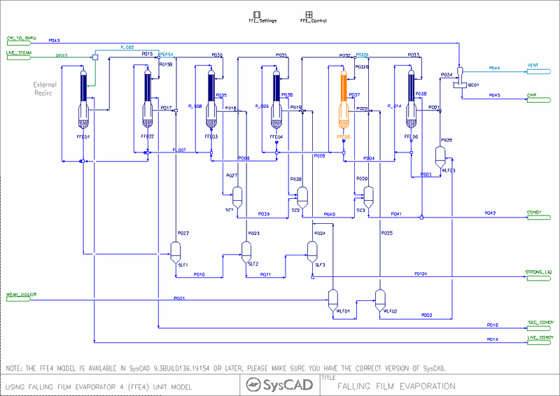
The main new functionality in this model is the ability to connect both evaporating and condensing sections to other flash train units, in particular other Falling Film Evaporators. The simplest cascade configuration is a series of FFE4 models, with the Tube Vapuor outlet of each connected to the next evaporator, and the Tube Liquor outlet connected to the previous evaporator. The Lead Evaporator is connected to a live steam demand source, and the final evaporator connected to a barometric condenser.
This model requires no further configuration or control, apart from setting demand steam conditions and baro condenser water supply.
Distributed Example Project
More complex models can include additional reflash on the condensate, heat recovery and other optimizations. Please see Alumina Falling Film Evaporation Example for more information.
Turning an Effect Off
User can set up a Multiple Effect circuit covering the maximum number of FFE units. The same circuit can be used to model less effects by switching certain FFE units offline.
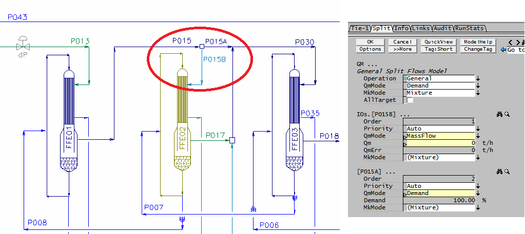
When a FFE unit is switched off, it will NOT condense any steam on the Shell side NOR Evaporate any vapour on the Tube side, so there will be NO steam supply to downstream units. If the FFE unit is part of a flash train, it will break the flash train. To fix this problem, user has to add a TIE unit to split the steam out in the upstream unit (N-1) and direct it to the downstream unit (N+1) Shell in, as shown in the image below:
The Tie configuration needs to be setup with a mode switch, (usually in a PGM file), in the above example:
- When the FFE unit is offline, [P015a] needs to be in demand mode and [P015B] needs to be set to 0 flow.
- When the FFE unit is online, [P015a] needs to be set to 0 flow and [P015B] needs to be in demand mode.
Please see the distributed example project for the PGM code for handling the configuration switch.
Troubleshooting Evaporator Models
With complex evaporator cascade models which may include additional flash tanks and condensate reflash pots, there may be some difficulty having the model solve at all. A good physical understanding of the interaction between the elements in a model is necessary.
For example, the following variant of the distributed alumina evaporation model uses three weak liquor flash stages rather than a heat exchanger and two flash stages: The incoming weak liquor is flashed in three stages to FFE05, FFE06 and the baro condenser. The outgoing strong liquor is flashed in three stages to FFE03, FFE04 and FFE05, as is the primary condensate to FFE04, FFE05, FFE06.
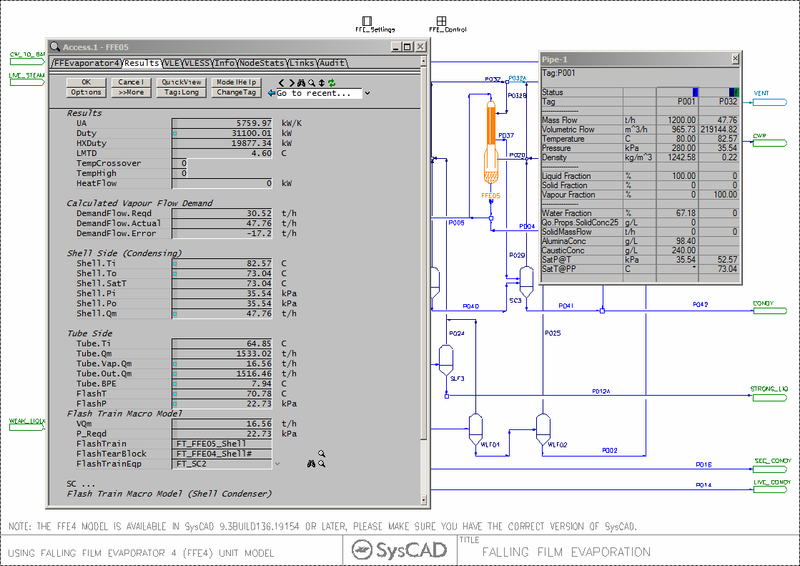
If this is run with incoming liquor at a low temperature, the model will show an error Demand Not Met on FFE05. Looking at the required and actual demand we find that the actual flow is much greater than the demand required:
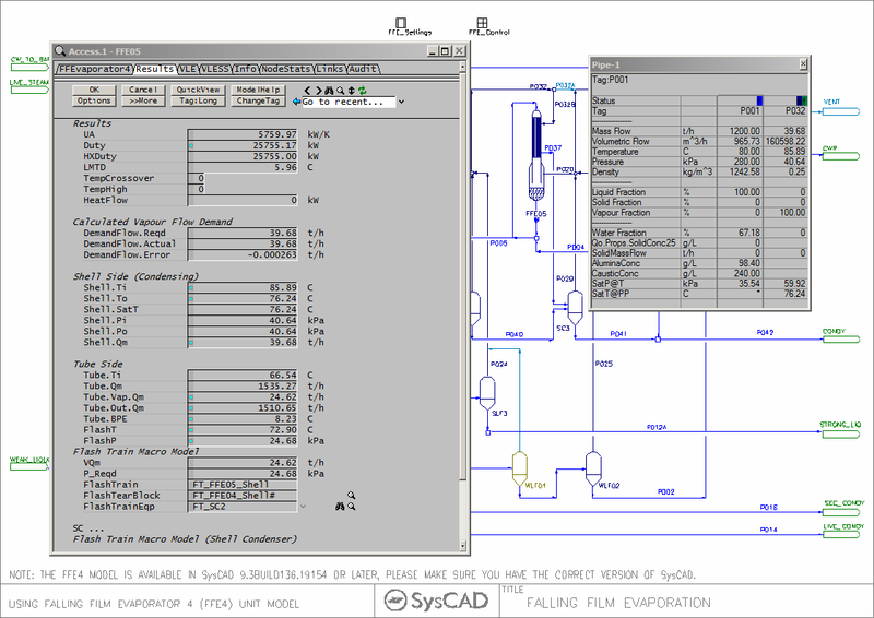
If you disable WLF01, then the model runs happily with no flow from WLF01.
The problem arises because the saturation pressure of the incoming weak liquor in P001 is less than the pressure in P032. Physically this means that this configuration would have vapour flowing into WLF01, which would effectively be acting as a barometric condenser using the cold incoming weak liquor!
With WLF01 on, the flash pressure is set at the minimum flash pressure of all the sources feeding FFE05, here 35.54kPa absolute. Then the demand calculated from the other sources (SLF3, SC2 and FFE04) is large (since we have such a low flash pressure). Physically, the DeandFlow.Error of -17.2tph would be flowing back to WLF01, heating the liquor out. Since the SysCAD flash macro model doesn't allow this, we end up with the Demand Not Met error since we push all the 47.76tph flow to FFE05 which is only "asking" for 30.52 tph.
This example illustrates the sort of subtle errors that can occur in FFE cascades and other complex flash train models, and why a good physical understanding of the overall model and how the components interact is necessary to find these sorts of errors.
Instability in FFE Cascade models
Sometimes the model will not converge, with the errors being flash pressures which are bouncing around. This often happens when the flows are low or the heat transfer or area high.
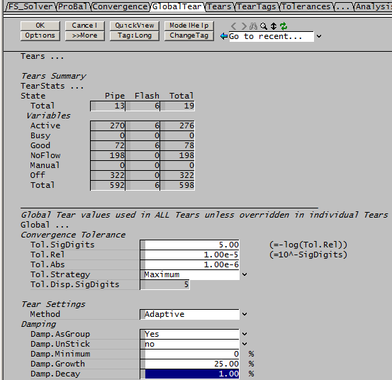
The problem is that the high demand in the flash macro models will lead to overshoot in the flash pressure estimates. The flash pressure changes are adaptively damped in the solver, but the damping may reduce too quickly (controlled by the tag $Solver.Tears.Global.Damp.Decay (%)); experiment with reducing this decay from its default of 5% to 1%:
This may however slow down convergence in other models, so it is better to change the values for the Flash Train tear settings individually on the Tears tab:
Example Projects
- Alumina Falling Film Evaporation Example - Feed is added at the cold end.
- Sugar Falling Film Evaporation Example - Feed is added at the hot end.
