Desuperheater
Navigation: Models ➔ Energy Transfer Models ➔ Desuperheater
General Description
The Desuperheater is designed to cool superheated steam by the addition of a water stream.
This unit can be used as part of a Flash Train, where a Desuperheater is in a steam line between a steam source and steam sink (e.g. Shell and Tube Heater). By adding water, the 'superheating' in the steam can be used to increase the steam volume flowrate while maintaining a similar temperature.
The best way to operate the de-superheater is to have the water stream in Demand mode. However, the user can also use it in the general mode so that constant water feed is supplied. Note: in this case, the outlet steam temperature may not be met. These 2 modes are described in Modes of Operation
Notes:
- If the desuperheater is used in a Flash Train, then it is recommended that the user enables the 'Strict' mode and also the 'AdjustWaterFlow' option - as this adds the correct amount of cooling water to achieve the requirements at each iteration. This improves the stability of the solution, and when the project is solved the actual amount of water added should equal the required amount of water.
- The Demand Project with Desuperheaters and Power Plant Example projects, which are distributed with SysCAD in the Examples folder, demonstrate the use of this model in a SysCAD project.
Diagram
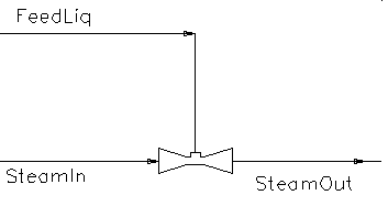
The diagram shows the default drawing of the Desuperheater, with the required connecting streams. The unit will not operate unless all of the above streams are connected.
The physical location of the connections is not important; the user may connect the streams to any position on the drawing.
Inputs and Outputs
| Label | Required Optional |
Input Output |
Number of Connections | Description | |
| Min | Max | ||||
| SteamIn | Required | In | 1 | 1 | The Superheated Steam feed. |
| SteamOut | Required | Out | 1 | 1 | The Desuperheated Steam Outlet. |
| FeedLiq | Required | In | 1 | 1 | The spray water stream. |
Behaviour when Model is OFF
If the user disables the unit, by un-ticking the On tick box, then the following actions occur:
- All streams connected to the inlets will be mixed, but NO evaporation will occur in the unit;
- All material will report unchanged to the SteamOut stream;
- If the Demand option has been chosen, no cooling water will be demanded;
- The cooling water flow required will be set to zero (in case an external controller is measuring this).
Note: Be careful not to add water when the model is off and high temperature steam is added. Water can not exist past the critical temperature of 373.15°C.
Model Theory
- The unit pressure is equal to the pressure of the incoming superheated steam.
- The Desuperheater attempts to achieve steam:water equilibrium at the unit pressure. In normal operation this will involve flashing all of the spray water to achieve the user defined conditions.
- The temperature and amount of material which changes phase is calculated using an adiabatic flash routine. Please see Vapour Liquid Equilibrium (VLE) for more information.
- The Temperature : Pressure curves for saturated steam is part of the SysCAD internal data. The equilibrium point will be that of saturated steam, as found in Steam Tables.
The user can specify the amount of superheat to be removed in the following ways:
- Temperature Drop. The maximum temperature drop allowed by the model is the difference between the amount of superheat of the incoming steam and the saturated temperature at the total unit pressure. If the user required temperature drop is greater than this value, the final temperature will be the saturated temperature and the unit will flag an error.
- Final Temperature. The maximum temperature allowed is the incoming steam temperature and the minimum temperature allowed by the model is the saturated temperature at the total unit pressure. If the user required final temperature is outside of this range, the unit will flag an error.
- Approach to Saturation Temperature. The user specifies the degrees above saturation of the exiting steam. The maximum approach allowed is the degrees of superheat of the incoming steam. If the user required approach is greater than this value, the unit will flag an error. The minimum approach allowed is zero.
- Saturated. The exiting steam is required to be at the saturated values at the unit pressure.
Water in Demand mode
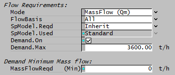
This is where the water feeder connected to the Desuperheater is set to Demand mode, as shown below:
When the Feeder is set up in Demand mode, the amount of water needed by the unit to achieve the required temperature is transferred to the connecting water line and delivered to the Desuperheater by the feeder.
Notes:
- The Feeder Mode can be either Source_ConstQm or Source_ConstQv
- Demand.On MUST be enabled
- If the value specified in the 'QmReqd (Min) / MassFlowReqd (Min)' field is larger than the calculated water requirement, the water fed to the Desuperheater will be in excess.
- The demand logic often works better if the QmReqd (Min) / MassFlowReqd (Min) field is a small number rather than zero.
General calculation mode
This is where the water connection to the Desuperheater is NOT in Demand mode. PGM code or a PID unit may be required to set the water flowrate to achieve the required temperature.
Note: The Desuperheater unit does display the amount of water required to achieve the desuperheating requirements, and this can be used to adjust the water flow to the unit.
Assumptions and Limitations
- The Desuperheater is a constant enthalpy, constant pressure process.
- The Steam line into the unit contains SUPERHEATED steam.
- The Liquid line into the unit contains water.
- When the water is in Demand Mode, the minimum outlet steam temperature will be limited to its saturation temperature.
- When the water is not in Demand mode, the outlet steam temperature can be reduced to below its saturation Temperature if too much spray water is added. When this happens, the steam outlet will not be in the correct state. Therefore, the spray water should be in Demand mode wherever possible. If this is not possible, use a PGM to get the correct required water flowrate (FlowReqd - calculated by SysCAD based on the required temperature change) and use it to set the water flow.
- If the user does enable the 'AdjustWaterFlow' and does not have the water in Demand mode, then there may be an imbalance when the project is solved. The unit will flag an error in this case.
Data Sections
The default sections and variable names are described in detail in the following tables. The default Desuperheater access window consists of 3 sections. This number may increase or decrease, based on user configuration.
- DesuperHeater tab - This first tab contains general information relating to the unit
- QProd - Optional tab, visible if ShowQProd is enabled. This and subsequent tab pages, e.g. QProd.. and Sp, shows the properties of the product stream. The tags in the QProd tab are valid even when the ShowQProd option is not selected.
- Info tab - contains general settings for the unit and allows the user to include documentation about the unit and create Hyperlinks to external documents.
- Links tab - contains a summary table for all the input and output streams.
- Audit tab - contains summary information required for Mass and Energy balance. See Model Examples for enthalpy calculation Examples.
Desuperheater Page
Unit Type: DesuperHeater - The first tab page in the access window will have this name.
| Tag (Long/Short) | Input / Calc | Description/Calculated Variables / Options |
| Tag | Display | This name tag may be modified with the change tag option. |
| Condition | Display | OK if no errors/warnings, otherwise lists errors/warnings. |
| ConditionCount | Display | The current number of errors/warnings. If condition is OK, returns 0. |
| GeneralDescription / GenDesc | Display | This is an automatically generated description for the unit. If the user has entered text in the 'EqpDesc' field on the Info tab (see below), this will be displayed here. If this field is blank, then SysCAD will display the UnitType or SubClass. |
Requirements | ||
| On | Tick Box | If this option is deselected, the desuperheater will not be operational and all material will report unchanged to the SteamOut stream. |
| TempSpec | Temp Drop | The user specifies the required temperature drop in the steam line.
Note: If the required temperature drop means that the final steam temperature would be below the saturated temperature, then a warning will be given and the final temperature will be restricted to the saturated temperature at the unit total pressure. |
| Final Temp | The user specifies the required temperature of the outlet steam.
Note: If the required final temperature is above the inlet steam temperature or below the saturated temperature, then a warning will be given and the final temperature will be restricted to either the saturated temperature at the unit total pressure or the inlet steam temperature. | |
| Approach SatT | The user can specify the approach temperature to saturation. Thus, if Approach SatT is 5, then Steam Exit Temperature = Saturation Temperature at total unit Pressure + 5.
Note: If the required approach is greater than the degrees of superheat of the inlet steam, then a warning will be given and the final temperature will be restricted to the inlet steam temperature. | |
| Saturated | The exit steam will be at the saturation temperature at the total unit pressure. This is equivalent to an Approach of 0. | |
| TempDropReqd / TDropReqd | Input | This field is only visible if the user selects Temp Drop for the TempSpec. The required temperature drop across the steam line. |
| FinalT_Reqd | Input | This field is only visible if the user selects Final Temp for the TempSpec. The final steam temperature required. |
| ApproachSatT | Input | This field is only visible if the user selects Approach SatT for the TempSpec. The approach temperature to the steam saturated temperature. |
| StrictReq / Strict | Tick Box | If this is enabled, then the user will receive a warning if the user required conditions are NOT achieved. It is expected that the General Demond logic or other control method will be used to adjust the cooling water flow rate to achieve the required conditions. |
| AdjustWaterFlow | Tick Box | This field is only visible if 'Strict' is enabled. If this is enabled, then the unit will either add or remove water to achieve the required conditions. This improves the stability of the solution, but it may also lead to a mass imbalance if the amount of water added to the unit is NOT equal to the required amount of water. It is expected that the General Demond logic or other control method will be used to adjust the cooling water flow rate to achieve the required conditions. |
Options | ||
| ShowQProd | Tick Box | QProd and associated tab pages (e.g. Qm) will become visible, showing the properties of the product stream. See Material Flow Section. This will be after any flashing occurs. |
| TrackPureSteam | TickBox | This adds a check for the composition of the Steam feed. If the line does NOT contain 100% steam a warning will be generated - Expect pure steam in steam feed. |
| TrackPureWater | TickBox | This adds a check for the composition of the FeedLiq stream. If the line does NOT contain 100% water a warning will be generated - Expect pure water in feed liquor feed. |
Results | ||
| Cooling water addition | ||
| FlowReqd | Calc | This is the required spray water flow calculated by SysCAD to achieve the specified outlet temperature. |
| ActualFlow | Calc | This is the Actual spray water flow entering the unit operation. |
| FlowReqdForSatT | Calc | This is the amount of spray water that is required to produce saturated steam at the total unit pressure. |
| Steam inlet | ||
| Steam.Ti | Display | This is the temperature of the steam entering the unit. |
| Steam.SatTi | Calc | The Saturation Temperature of the Steam entering the unit. |
| Steam.DegSuperHeat | Calc | The degree of superheat of the steam entering the unit. (The saturation temperature is calculated at the total unit pressure = steam feed pressure). |
| Steam.Pi | Display | The pressure of the feed steam. |
| Steam.Vfi | Display | The steam fraction in the feed steam (normally 100%). |
| SteamInFlashed | Tickbox | This will be enabled if the steam entering the unit contains any liquid water to indicate to the user that the water has been flashed. |
| FlashSteam.Ti | Display | This is the temperature of the steam after it has been automatically flashed. If there is no water in the feed stream, this will be the same as the temperature of the steam entering the unit. |
| FlashSteam.DegSuperHeat | Calc | The degree of superheat of the steam after it has been automatically flashed. If there is no water in the feed stream, this will be the same as the degree of superheat of the steam entering the unit. |
| Steam outlet | ||
| TDrop | Calc | The temperature drop of the steam across the unit. |
| FinalT / To | Calc | This is the temperature of the steam leaving the unit. |
| FinalSatT / SatT | Calc | The Saturation Temperature of the steam leaving the unit. |
| DegSuperHeat | Calc | This is the degree of superheat the steam outlet contains. |
| FinalP / Po | Display | The pressure of the steam leaving the unit. |
| FinalVapourFrac / Vfo | Calc | The vapour fraction in the stream leaving the unit. |
| Dmnd.... Demands Table: (shows both steam and water demand for the desuperheater) | ||
| The Table will have the following headings for Feed streams. | ||
| Demands | Display | The amount of flow required to entering the Desuperheater, this is based on the amount demanded by downstream units |
| Ft.Demand | Display | Flash Train demand, only valid if the unit is part of the flash train |
| Actual | Display | The actual flow into the Desuperheater. |
| ConnTag | Display | The stream Tag name. If the stream is connected to a source unit, then (Src) will be shown to the right of the column. |
| The Table will have the following headings for product streams. | ||
| Demands | Display | The amount of flow leaving the Desuperheater, the stream flow is based on demand by downstream units |
| Ft.Demand | Display | Flash Train demand, only valid if the unit is part of the flash train |
| Actual | Display | The actual flow exiting the Desuperheater. If the actual flow available is greater than demand flow, the actual flow might be different to demand flow. |
| ConnTag | Display | The stream Tag name. |
Hints and Comments
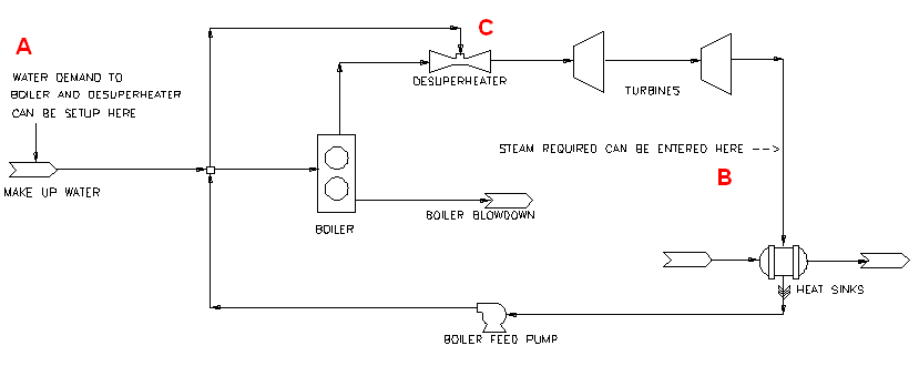
How to set up the desuperheater in a power plant circuit:
- A: Set up the feeder with Demand.On selected.
- B: On the steam outlet pipe (this can be any pipe downstream of the Boiler), set up the Qm_Demand.Reqd flowrate.
- C: The desuperheater can pass on demand on the steam side, and based on the steam flow and desuperheater temperature setting, work out the correct amount of water needed to desuperheat the steam.
Adding this Model to a Project
Add to Configuration File
Sort either by DLL or Group:
| DLL: | HeatXch1.dll |
→ | Units/Links | → | Heat Transfer: Desuperheater | |
| or | Group: | Energy Transfer |
→ | Units/Links | → | Heat Transfer: Desuperheater |
See Model Selection for more information on adding models to the configuration file.
Insert into Project Flowsheet
| Insert Unit | → | Heat Transfer | → | Desuperheater |
See Insert Unit for general information on inserting units.
Example Project
Please see Demand Project with Desuperheaters and Power Plant Example projects.


