Example Power Plant Projects
Navigation: User Guide ➔ Example Projects ➔ 55 PowerPlant
Demand Project with Desuperheaters
Project Location
This is a Steady State project and is stored at:
..\SysCADXXX\Examples\55 PowerPlant\Demand Example(with desuperheaters).spf
Features Demonstrated
- Demand in Pipes and Feeders.
- Using saturated and super-heated steam.
- Desuperheater
- Flash Tank
- Example Stream Report.xls
Brief Description
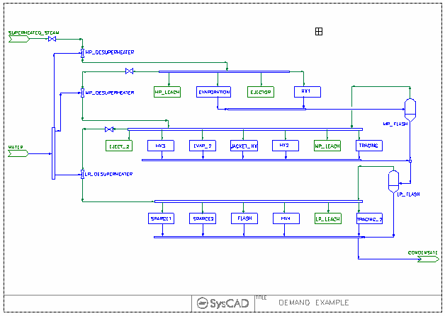
The project shows an overall view of steam usage in a plant.
- The plant is supplied with a single source of super-heated steam.
- The steam is used in the plant at three different pressures, all requiring saturated steam.
- The saturation is carried out in Desuperheaters after the pressure has been reduced across a Valve. The amount of water added is controlled by the Desuperheater via the Demand logic.
- The steam requirement for each area of the plant is set in the Demand section of the pipe feeding the area.
- A reaction block in each area condenses the steam to water while maintaining the temperature at a constant value. This emulates the conditions in the plant, where the energy from the condensation is taken up with heating requirements.
- Condensate from the higher pressure and temperature steam is flashed in a Flash Tank to recover steam at the next lower temperature steam required. The steam recovered joins up with the fresh steam feed.
- The General Controller sets the temperature and pressure of the feed steam, as well as the required pressures for the HP, MP and LP steam.
A similar project not using the desuperheater process model is also available, see Demand Project
Project Configuration
- Steam Supply Feeder
- The SuperHeated_Steam Feeder in this project will provide all the steam demanded by downstream processes.
- Feed_XPG-1 Tab, Select Demand.On, check that Demand.Max will cover the flowrate range for the project. Increase this value if necessary.
- Qm_Rqd will represent the minimum value for the steam supply. If this value is higher than downstream requirements, the excess amount is distributed. Recommend using a small number of this field.
- Define the operating condition and composition.
- SysCAD will calculate the feed flowrate and display it in the Results:Flow Conditions Qm field.
- The SuperHeated_Steam Feeder in this project will provide all the steam demanded by downstream processes.
- Desuperheating Water Supply Feeder
- The DesuperHeating WATER Feeder in this project will provide all the water demanded by desuperheaters.
- Set up this unit as per the steam feeder above.
- Desuperheaters
- The Desuperheaters are set to achieve Saturated conditions.
- The pressure is defined by the valve feeding the desuperheaters,
- DemandConnection is set to General Demand, this together with the WATER feeder put on Demand mode, will auto add just enough water to give the saturated conditions.
- Compare this with the Demand Project, this eliminates the need for PID + Condensing reactions in the desuperheating section.
- The Desuperheaters are set to achieve Saturated conditions.
- Steam Users
- When defining the steam users / steam distribution, it is important to NOT use the SPLITFLOW options in Tanks/Ties. The distribution of steam should be specified in PIPES.
- For Example, for the HP_Steam_Distributor,
- SplitFlows is NOT selected.
- Outlet Pipes S009 to S012 have steam demand requirements defined in the Pipe-1 Tab, under Qm_Demand.Rqd field.
- HP_Steam_Distributor Tie-1 Tab shows a summary table of the stream demand values.
- It is important that EVERY steam user amount is defined, this will allow the calculation of the total feed required.
Included Excel Report
Steam Report.xls - This file includes Steam Diagram and Streams report.
Power Plant Example
Project Location
This is a Steady State project and is stored at:
..\SysCADXXX\Examples\55 PowerPlant\Power Plant Example.spf
Features Demonstrated
Brief Description
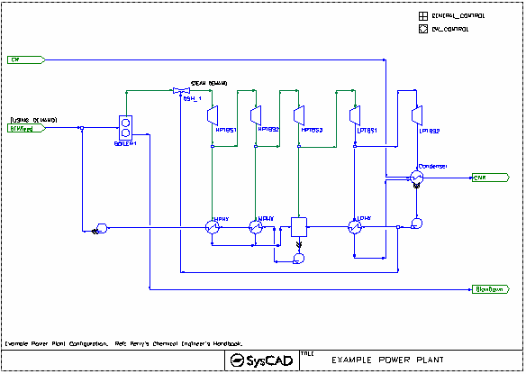
This is a simple closed loop power plant circuit, with 1 boiler, 5 turbine extraction stages, heat sinks (condensers) and Boiler water feed make up. This project also contains some simple side calculation for Fuel usage (found in the General controller.)
Project Configuration
- Boil Feed Water top up amount balances the losses in the boiler, this is done via the PGM controller.
- Boiler - define final T&P, efficiency and blowdown
- Turbines - define pressure and efficiency. The Steam produced maybe superheated or two phase saturated.
- All heat exchangers are set in fully condensing mode, with Area and HTC defined. The CondenseAll option is selected to unsure all the steam is condensed should the specified area is too small. The actual area required is shown in the TheorArea Field.
- Fuel calculation are done via the PGM controller as a side calculation.
Rankine Cycle Example
Project Location
This is a Steady State project and is stored at:
..\SysCADXXX\Examples\55 PowerPlant\Rankine Cycle Example.spf
Features Demonstrated
Brief Description
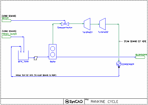
This is a simple open loop power plant circuit, with 1 boiler, desuperheater, 2 turbine extraction stages and condenser. Shows the simple steam-plant-cycle and generation of electric power and process steam.
Project Configuration
- Desuperheating Water Supply Feeder
- The DesuperHeating WATER Feeder in this project will provide water demanded by desuperheaters.
- FeederSink Tab, Select Demand.On, check that Demand.Max will cover the flowrate range for the project. Increase this value if necessary.
- QmReqd will represent the minimum value for the steam supply. If this value is higher than desuperheater requirements, the unit will report an error.
- Define the water condition and composition.
- SysCAD will calculate the water flowrate and display it in the Results:Flow Conditions Qm field.
- The DesuperHeating WATER Feeder in this project will provide water demanded by desuperheaters.
- Desuperheaters
- The Desuperheaters are set to achieve a target Final Temperature.
- DemandConnection is set to General Demand, this together with the WATER feeder put on Demand mode, will auto add just enough water to give the required temperature.
- Others
- The configuration of Boiler, Turbine and condenser are as per project Power Plant Example
Cogeneration Example
Project Location
This is a Steady State project and is stored at:
..\SysCADXXX\Examples\55 PowerPlant\Cogeneration Example.spf
Features Demonstrated
Brief Description
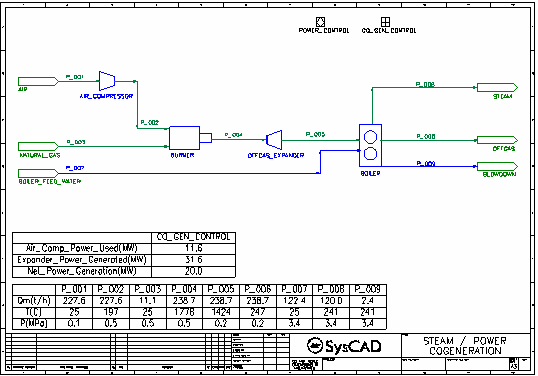
This is a simple cogeneration plant with an air compressor, burner, expander and boiler. Shows the generation of electric power and process steam.
Project Configuration
Most of the configuration of the model is set by the Co_Gen_Control General Controller. The parameters on the three tabs of the controller are described below:
- Feeds tab
- The user can specify the Air feed temperature, pressure, N2 and O2 composition and excess air as a percentage of the required air for complete combustion of the natural gas. The controller calculates and sets the flow of air to achieve the specified excess air.
- The user can specify the Natural Gas feed temperature, hydrocarbon, CO2 and N2 composition.
- The Burner Feed Pressure is specified by the user. This sets the air compressor outlet and natural gas feed pressures.
- The user specifies the Boiler Feed Water temperature.
- Power tab
- The user specifies the air compressor efficiency, which is passed to the air compressor model.
- The user specifies the expander (modelled by a compressor unit model) efficiency and outlet pressure. The outlet pressure is passed to the expander model while the efficiency is used for power calculations within the controller.
- The user specifies a Target for Power Generation and this becomes the setpoint for the Power Control PID Controller, which varies the natural gas feed flow to achieve the target power.
- The controller calculates the net power generated which takes account of power required for air compressor and the efficiency of the expander. This is the measured value for the Power Control.
- Steam tab
- The user can specify the required steam pressure and the pressure drops from the Boiler Feed Water to the Drum and from the Drum to the Steam Pressure. Based on these settings the controller sets the Boiler Feed Water and Boiler Drum pressures.
- The user specifies the boiler efficiency and blowdown which are then passed to the Boiler model.
- The user specifies a target steam mass flow and the boiler feed water mass flow is set based on this target after taking account of the loss due to blowdown.


