PID Controller
Navigation: Models ➔ Control Models ➔ PID Controller
| General Controller | PID Controller | Ratio / SetTag Controller |
|---|
Related Links:Controls Window, Controls, PGM Example: Optimise Gain
General Description
The PID Controller (Proportional–Integral–Derivative controller) unit is used to simulate simple PID plant control functions. If the user requires more complicated controls that involves data manipulation, then the General Controller can be used to assist the PID control. For example, user may want to calculate the setpoint as a function of temperature, or change the output range as a function of plant feed.
- A single PID controller unit can be used to simulate a number of independent PID controllers on the plant. The user may enter the required number of PID controllers in the Count field on the first page of the Access window.
- The control logic used to manipulate the variables is executed once at the end of each SysCAD iteration.
- The PID controller may be used in Steady State or Dynamic mode.
- In Dynamic mode it closely simulates an actual plant PID loop.
- In Steady State mode the time dependent factors are not used in the traditional manner, instead each iteration is treated as a "one second time increment".
The Referenced Tags
The PID Output tag and the Measured tag, will have coloured triangles shown in the access window of those units. When the user right clicks on one of these referenced tags it will indicate which PID is referencing the tag. See Controlled and Referenced Variables.
Convergence in Steady State
- In Steady State, the requirement for the measured value to equal the set-point is included in the convergence criteria. Therefore, the SysCAD Steady State solver will continue with iterations until Tolerance Testing calculation is met within the defined tolerances in the same way that Tear Recycle stream criteria are tested.
- If the output of a controller is at its minimum or maximum output limit, then the PID is excluded from these criteria and the solver can stop even though the set-point is not achieved. This is because the output can no longer influence the measured value to achieve the required set-point value. A condition error message is given to alert the user to this.
- Please refer to section Hints and Comments for more comprehensive hints on how to troubleshoots the controller, user can also have a look at the video links below for how to add and troubleshoot the controllers used in the tutorial project.
- For sensitive controllers such as pH controls, user can add some PGM logic to change the gain based on relative error of the control. Please see PGM Example - PGM Class to assist with solving sensitive PID control loops for the PGM Class and how to add it to a PGM file.
Video Links
The following videos are part of the Tutorial showing users how to use PID Controllers:
Diagram
![]()
The diagram shows the default drawing of a PID controller.
This screen dump shows variables used and calculated in the PID Controller. (Example PID from the Tutorial)

Inputs and Outputs
There are no connections to this unit.
Model Theory
The classical PID algorithm as shown below is used in the model:
- [math]\displaystyle{ u(t) = K \left[e(t)+\cfrac{1}{T_i}\int e(t)dt + T_d\cfrac{de(t)}{dt}\right] }[/math]
where [math]\displaystyle{ u(t) }[/math] Control action or output variable at time t in seconds [math]\displaystyle{ e(t) }[/math] the error (or deviation) [math]\displaystyle{ w(t) - y(t) }[/math] : the difference between the set point [math]\displaystyle{ w(t) }[/math] and the measured variable [math]\displaystyle{ y(t) }[/math] [math]\displaystyle{ K }[/math] Controller gain [math]\displaystyle{ T_i }[/math] Integral time [math]\displaystyle{ T_d }[/math] Derivative time
For a full description of the theory, please see the reference below.
References
Clarke D.W, PID Algorithms and their computer implementation, Dept of Engineering Science, University of Oxford Trans Inst M C Vol 6 No 6 Oct-Dec 1984
The Wikipedia page on PID Controllers also well describes the basic concepts, and contains a number of external links to useful sites.
Applying the Measured and Output Range
- Each PID implementation works on normalised values. So the measured and setpoint values are scaled between 0 and 1 where 0 is InMin and 1 is InMax. The PID algorithm then works in this scaled values. This scaling needs to be taken into account when computing the effective open loop gain of the process as seen by the PID controller.
- MeasScaled = (Meas-InMin)/(InMax-InMin)
- SetpointScaled = (Setpoint-InMin)/(InMax-InMin)
- The PID algorithm is performed on the scaled values and calculates OutScaled.
- Then OutScaled is converted to final Output value to be set based on the Output Range:
- Output = OutMin+OutScaled*(OutMax-OutMin)
The Error term, shown as tag RelError, is calculated as SetpointScaled - MeasScaled which is the same as (Setpoint-Meas)/(InMax-InMin)
SetPoint at or near measured limits
- The SetPoint for the PID should be within the measured range. Ideally this should not be "close" to the limits as this does not give a significant error term and hence the PID action can be "inefficient". This setpoint tolerance for "close" is 10% relative to the user specified measured minimum and maximum. SysCAD gives a warning message when the setpoint value is within this tolerance of the defined measured minimum or maximum.
- In SysCAD, to still give a reasonable error term to drive the PID action when the setpoint is within tolerance of the measured limits, an adjusted measurement minimum or maximum is used.
- A value equal to the setpoint value less 10% is used for measured minimum when the setpoint is close to the user specified measured minimum.
- A value equal to the setpoint value plus 10% is used for measured maximum when the setpoint is close to the user specified measured maximum.
- Therefore the MeasScaled described above is adjusted accordingly.
- In the special case where the setpoint is equal to the measured limit and also equal to the measured value, then the PID output is set to the output minimum or maximum (according to measured limit and reverse action). This is because the setpoint has been met and there is no error term to drive the output (and hence any previous output may appear correct when in fact an alternate output value is expected).
Data Sections
The default PID Controller access window consists of 3 sections. The number of sections in the access window will depend on the number of independent PID controllers required by the user.
Each independent PID controller is displayed on a separate page.
Summary of Data Sections
- PID tab - Contains a summary of all of the individual PIDs contained in the unit.
- P1 tab - Each individual PID has its own page - starting at 1 for the first PID. This page contains all of the information for each individual PID.
- Info tab - Contains general settings for the unit and allows the user to include documentation about the unit and create Hyperlinks to external documents.
Unit Type: PID - The first tab page in the access window will have this name.
PID
| Tag (Long/Short) | Input / Calc | Description/Calculated Variables / Options |
| Tag | Display | This name tag may be modified with the Change Tag option. |
| Condition | Display | "OK" if no errors/warnings, otherwise lists errors/warnings. |
| ConditionCount | Display | The current number of errors/warnings. If condition is OK, returns 0. |
| GeneralDescription / GenDesc | Display | An automatically generated description for the unit. If text is entered in the 'EqpDesc' field on the Info tab (see below), this is displayed here. Otherwise, SysCAD will display the UnitType or SubClass. |
| On | Tick Box | The Overall PID unit will be enabled or disabled using this box. This means that all of the independent PID controllers in the unit will be disabled. |
| ShowCnv | Tick Box | With this option selected, SysCAD will display engineering units for tags such as Spt, Meas, Output, InMin/Max and OutMin/Max. Note that these will only be displayed after SysCAD has completed at least one iteration. |
| Count | Input | The number of independent PID controllers required. This may be any number from 1 upwards. The user may also change this number at any time. The unit will always add new PID controllers after existing ones. The user may delete individual PIDs using the 'Delete Me' button. |
| Check Tags | Button | SysCAD will perform a check on the validity of the tags and functions used in the PID controllers. |
| Summary This shows two summary tables with the following values for each individual PID in the unit.
| ||
| First Summary Table: | ||
| PID | Display | The PID number |
| On | Tickbox | The user may enable or disable each individual PID on the first page. |
| SptUsed | Display | The actual set point for the individual PID. |
| Meas | Display | The measured value for each individual PID. |
| OutUsed | Display | The output value for each individual PID. |
| RelError | Display | The relative error for each individual PID - i.e. the error between the set point and the measured value. Calculation is: (SptUsed-Meas)/(InMax-InMin) |
| Second Summary Table: | ||
| PropBand | Input | The Proportional Band (inverse of the Gain) for each individual PID. The user may change this value here or on the page for the individual PID. |
| SptUnitTag | Display | The SysCAD Tag used for the SetPoint. Only visible if one or more of the PIDs have the UseSetPointTag option enabled. |
| MeasUnitTag | Display | The SysCAD Tag used for the Measured Value. |
| OutputUnitTag | Display | The SysCAD Tag used for the Output Value. |

P1: Individual PID Data Fields
Each independent PID is displayed one per page.
| Tag (Long/Short) | Input / Calc | Description |
|
Tag.Cfg.[PID number] | ||
| On | Tick Box | This can be used to enable or disable the independent PID. |
| Name | Input | The user may give the PID a short tag name that describes the control, following the same rules for Model Tags, e.g. Autoclave_Steam. |
| Index | Input | PID Control block Index. Useful for sorting the controllers in reports. |
| ID | Input | The user may use this field to display a reference controller ID, useful for reports or matching plant data. |
| Type | Clarke | This method is recommended for most applications. |
| Clarke FF | This method refers to controller Direct/Reverse acting in the form of Process Gain, as well as having extra fields such as Bias for Proportional control and Feed Forward cross reference. | |
| Description | Input | The user may enter a description of the PID controller as text. This field is handled by SysCAD like a normal tag, therefore it can reported and set via Excel. |
| UseSetPointTag | Tickbox | If this is enabled, then the user can use a SysCAD tag/function as the setpoint. If this is not ticked, then a constant value is expected for the setpoint. |
| Current values | ||
| SetPointValueUsed / SptUsed | Output | The Set Point value used. The value is either a fixed user defined Set point value or it changes according to the user defined Set Point Tag. |
| MeasuredValue / Meas | Output | The measured variable, or more commonly called the Process Variable or PV. The PV is measured and acts as an input to the Controller which takes action based on the value of the PV. Alternatively the PV can be measured and displayed so that the operator can perform manual control. |
| OutputValueUsed / OutUsed | Output | The current value of the Controller Output Signal (OP). |
| RelativeError / RelError | Output | The relative error - i.e. the error between the target set point and the measured value. |
| CvgError | Output | Available from Build 139.34400. Only visible in Steady State projects. This is the Normalised Relative Error calculated as described in Tolerance Testing for the purpose of meeting solver convergence criteria. Note that calculation is performed based on units of measured and setpoint tags, which may not be SysCAD SI Units. If CvgError<1 then the PID is considered converged (measured value is close enough to set point). |
| CvgState | Display | Only visible in Steady State projects. The state of convergence criteria for this PID for use in overall solver convergence criteria. Useful for reporting the current state of the controller. The applicable states for PID convergence are:
|
| SetPoint | ||
| SetPoint / Spt | Input | The Target Value of the Process Variable (Meas), it should be between the minimum and maximum input values. Note: This field is only visible if the UseSetPointTag option is Disabled. |
| SetPointTag | Input |
This can either be a SysCAD tag or a function:
The value of the calculated set point will be displayed in the SetPoint box. |
| Measured tag (input) and expected range | ||
| MeasTag | Input | The Measured variable (sometimes called the Process Variable or PV). The Measured variable acts as an input to the Controller which takes action based on the difference between the Measured variable and the Set Point. The Measured variable can either be a valid SysCAD tag or a function. If it is a function, the first character must be an '=' followed by a valid expression. See the PGMs documentation for the required syntax. |
| MinimumInput / InMin | Input | The expected minimum value of the Measured variable. If the relative difference between this Minimum value and the Set Point is too small, SysCAD will flag a warning and adjust the range that is used to carry out the control. See Hints and Comments for more information. |
| MaximumInput / InMax | Input | The expected maximum value of the Measured variable. If the relative difference between this Maximum value and the Set Point is too small, SysCAD will flag a warning and adjust the range that is used to carry out the control.
Note: If the actual value of the Measured variable moves outside of these expected values, the controller will not operate efficiently. See Hints and Comments for more information. |
| FeedForwardTag | Input | Only appears for Method Clarke FF: Cross reference tag that specifies the amount of feedforward in units of the control output. Typically this value would be calculated in another controller. |
| Controlled tag (output) and range limits | ||
| OutputTag | Input | The tag that the PID Controller will set, or the Output Signal (OP). This must be a valid SysCAD tag that can be adjusted by the user, i.e. it MUST be a white field. |
| OutputValue / Out | Input/Output | The current value of the Controller Output Signal (OP). This is an input field when the model is stopped or if the PID is in manual mode. |
| MinimumOutput / OutMin | Input | The minimum value that the PID controller may send to the Output tag, or Output Controller Signal (OP). Ignored if PID is in manual mode. See Hints and Comments for more information. |
| MaximumOutput / OutMax | Input | The maximum value that the PID controller may send to the Output tag, or Output Controller Signal (OP). Ignored if PID is in manual mode. See Hints and Comments for more information. |
| Settings | ||
| Auto | Tick Box | This emulates the auto/manual function of a controller. If this option is switched off, then the controller is in manual and will no longer control automatically. Instead, the user may set the output of the controller to a fixed value. This value may exceed the output range. |
| SptTrk | Tick Box | This field only appears in a dynamic project. If the controller is in manual (Auto check box is unchecked), then if this option is switched on, the setpoint of the controller will set to the measured value. |
| TrackMinMaxMeas | Tick Box | This field only appears in a dynamic project. If this option is disabled then the user will stop receiving warnings when the measured value is outside the specified range of InMin to InMax. |
| TrackMinMaxOut | Tick Box | This field only appears in a dynamic project. If this option is disabled then the user will stop receiving warnings when the output value is at either of the specified limits (OutMin or OutMax). |
| ReverseActing / Reverse | Tick Box | The direction in which the PID controller will operate.
For Method - Clarke: This refers to the process response, which is opposite of what the control engineers' definition of process gain. For example, for this model to work properly, the line of thinking should be as such: 1) Steam is added ↑ to raise ↑ the temperature in the tank. So the process response in the same direction, thus this should be left un-ticked. 2) Cooling water is added ↑ to reduce ↓ the temperature in the tank. So the process response is in the opposite direction, thus this should be ticked. For Method - Clarke FF: Direct/Reverse Acting is implemented in the traditional way, thus opposite of what the Original and Clarke method does. 3) Reverse Acting (SP - PV) Used when the process gain is +ve. A process measurement increase causes a control output decrease. For example Inlet Flow to Tank Level - if the Tank Level is above Setpoint then we need to reduce the inlet flow. 4) Direct Acting (PV - SP) Used when the process gain is -ve. A process measurement increase causes a control output increase. For example Outlet Flow to Tank Level, if the Tank Level is above setpoint we need to increase the outlet flow. |
| Gain | Input | This uses the Proportional Control which is the main and principal method of control. It calculates a control action proportional to the error. Where Error is the difference between PV and SP. The Gain is applied to scale the size of the control action based on error. Using Proportional Control alone cannot eliminate the error completely.
Gain represents the power of the control action. The larger the Gain, the stronger the control (or more difficult to control). Therefore, user must not use a Gain larger than really necessary as it affects the stability of the process. If the Gain is set to zero, the controller becomes Integral (Pure I) only. |
| PropBand | Input | The proportional band (PB) of the Proportional control. It is calculated as PB(%) = 100 / Gain. User only need to enter values for either Gain or PB, the other is calculated using the above formula. See Hints and Comments for more information. |
| Integral | Input | The integral time constant of the Integral control. Integral control is used to control towards no error, thus to assist the Proportional control. Its value is set to max(Integral,Period/2) where Integral is the selected integral reset time and Period is the period of execution (equal to step time in dynamic and 1 in ProBal) of the PID controller.
See Hints and Comments for more information. |
| Derivative | Input | The derivative time constant of the Derivative control. Derivative control is used to add stability. Note: This is generally only used in Dynamic mode. This would normally be 0 in ProBal mode. |
| Bias | Input | Only appears for Method Clarke FF:
For proportional controllers only. The controller output will equal bias when the error is zero, thus bias is adjusted so that the controller output are at their nominal steady state value. It has the same units as the control output. |
| Options | ||
| TrackSptRange | Tick Box | If this option is disabled then the user will stop receiving warnings when the setpoint value is close to the limits of the specified range of InMin to InMax. |
| Tune Rule | Input | The user may select a tuning rule to use when automatic tuning is used. The user may select between Proportional only (P), Proportional and Integral (PI) or Proportional, Integral and Derivative (PID). |
| FeedFwd | Output | Only appears for Method Clarke FF: The value corresponding to that specified in the FeedForward_Tag. |
| Buttons | ||
| Delete | Button | This allows the user to Delete the current individual PID. Please note that there is no 'Undo'! |
| MoveUp | Button | This allows the user to increase the Priority of the current individual PID. For example, if the current PID is number 3, the user can change it to 2 or 1 by clicking on this button once or twice. |
| MoveDown | Button | This allows the user to decrease the Priority of the current individual PID. For example, if there are 3 PIDs in the unit and the current PID is number 1, the user can change it to 2 or 3 by clicking on this button once or twice. |
| Control Tolerances (Only visible in Steady State projects) | ||
| Tol.SigDigits | Input | Relative Tolerance in the form of Significant Digits. SigDigits = -log(Tol.Rel).
|
| Tol.Rel | Input | Relative Tolerance, allows user to loosen or tighten the control.
|
| Tol.Abs | Input | Absolute Tolerance, allows user to loosen or tighten the control.
|
| Referenced Units | ||
| SetPointUnitTag | Output | Returns the Unit Tag for the Set Point Variable, if used. |
| MeasUnitTag | Output | Returns the Unit Tag for the Measured Variable. |
| OutputUnitTag | Output | Returns the Unit Tag for the Output Variable. |
Adding this Model to a Project
Add to Configuration File
Sort either by DLL or Group:
| DLL: | Control1.dll |
→ | Units/Links | → | Control: PID | |
| or | Group: | General |
→ | Units/Links | → | Control: PID |
See Model Selection for more information on adding models to the configuration file.
Insert into Project Flowsheet
| Insert Unit | → | Control | → | PID |
See Insert Unit for general information on inserting units.
Hints and Comments
- If one of the PID controllers contains a tag that is invalid, SysCAD will flag that user that there is an error in the PID controller. Check the Messages window for a list of the invalid tags.
- If a PID controller ceases controlling, it may be that the measured or output variable is outside of the user defined minimum and maximum values.
- If this is the case, user should see warnings in the message window - solver conditions tab:
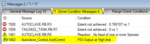
- To fix the errors, check the measured and output ranges and adjust the minimum or maximum values so that the measured/output variable falls within the limits.
- If this is the case, user should see warnings in the message window - solver conditions tab:
- HINT: "How to set up the PID to handle large setpoint ranges?", this may be required for scenario testing runs.
- Use a general controller (PGM file) to assist the PID control. Set up PGM logic to set some of the following based on user-defined logic:
- Measured Tag Min and Max Range (e.g.: use some known ratios to estimate the input range)
- Output Tag Min and Max Range (e.g.: use some known ratios to estimate the output range)
- Proportional band (e.g.: set up some user logic to change the Propband (or gain) based on error, can set the loop to be fast when it is far away from the solution, then slower then it is near the solution)
- Please note that some tags can only be adjusted when the project is not solving, such as controller on/off, SetPointTag, MeasureTag, OutputTag etc.
- Use a general controller (PGM file) to assist the PID control. Set up PGM logic to set some of the following based on user-defined logic:
- If the response of a independent PID is too fast, it will bounce around and never converge.
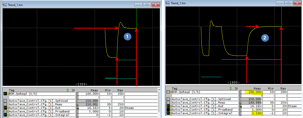
- User should always take advantage of the Trend Window while tuning the control loops.
- Suggest starting by increase the proportional band (or decrease the gain) until the response settles down, hint: watch the response from the trend window as you adjust the values and run the project.
For example, let's look at the acid controller from the Tutorial project (Chapter 6 of the tutorial). - If we didn't change the PropBand from its default value (5), we will find that this controller is too sensitive, we need to use smaller step change to keep it in control. To reduce the step change, we can increase propband (reduce the gain).
- We can increase the PropBand to a value that the solution can be found quickly. We can see this from the above picture that with a slower loop, we were able to find a solution.
- If changing the PropBand alone doesn't stabilise the solution, user should double check that:
- the control logic is correct, thus, the controlled variable (output tag) will have an effect on the measure tag.
- the measure variable and setpoint are using the same engineering units.
- the measured value is within range, and
- the output value is ranged sensibly. For example, if we only need to add 20 t/h acid, then we should not set the output maximum to 500 t/h, as this will cause the step size to be too big, and a solution may not be found.
- Each PID implementation scales the measured variable and control output between 0-100%. The PID algorithm thus works in this scaled range. This scaling needs to be taken into account when computing the effective open loop gain of the process as seen by the PID controller.
- Process Measurement Scaling : Kin = 100/(Inmax-Inmin)
- Control Output Scaling : Kout = (Outmax-Outmin)/100
- Process Gain with Eng Units : Ku
- Unitless Process Gain as Seen by PID : K = Kout*Ku*Kin = (Outmax-Outmin)/(InMax-InMin)*Ku
- See Process Gain for an example calculation.
- User can choose to use "P" control or "PI" control for Steady state projects.
- Some loops only require proportional control, so user may only need to adjust the Gain (or Proportional band). (The acid control above is such an example).
- Some loops can benefit by adding integral control, (thus PI control). PI control helps to remove the offset (error). (The steam control from the tutorial is such an example)
- user should watch the trend to get the desired response, such as should we allow for overshoot (can be faster see
 ), we can remove the overshoot, but can make the loop slower
  , so user should tune the loop to best suit their situation
  allows for small overshoot while keeping the loop relatively fast.
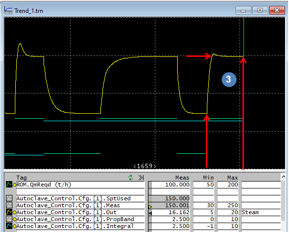
- In the above example, we have eliminated the overshoot by using PI control.
- User can adjust the P and I constants (by observing the response) until the desired output is achieved.
- HINT: when tuning a loop, it is always a good idea to test some setpoint changes to make sure the loop can handle any expected flow changes. Also, as the flowsheet changes (by adding more complexity), user will need to revisit the control loop and tune it again.
- Always analyse the circuit to help with control decisions, for example,
- some control loops are local, such as adding water to get certain solids fraction, these should be fast acting loops;
- some control loops such as production control will affect the entire balance, these should be slow acting loops, we need to allow the circuit enough time to adjust to the change.
- if user do not pay attention, they can end up with a project that just oscillates and never solves.
- Users can take advantage of the controller auto-tuning functionality to help tune controllers in the project. This often result in projects converging much faster with well tuned controls and is especially useful if many controllers have been used. To find out how, please refer to Controls Window.
- Auto tuning should be used with caution. Keep in mind that auto-tune is normally carried out while holding everything else steady, so results from Auto-tune may be too fast for the project. As a rule, always do manual set point change to test the loop tuning.
- Not all loops are suitable for auto-tune. Loops with large lag time (due to recycle or control variable is very far away from the measured variable) is hard to auto-tune. Recommend manual tuning.
- Control engineers using SysCAD may complain that the PID controller Direct / Reverse action is opposite to what they are used to. This is due to the fact that SysCAD uses the process response to determine the direction, not the process gain. For example, for this model to work properly, the line of thinking should be as such:
- a) Steam is added ↑ to raise ↑ the temperature in the tank. So the process response in the same direction, thus this should be left un-ticked.
- b) Cooling water is added ↑ to reduce ↓ the temperature in the tank. So the process response is in the opposite direction, thus this should be ticked.
- The problem above can be rectified by selecting the newly implemented method 4-Clarke FF under Type. Reverse Acting (SP - PV) Used when the process gain is positive. Direct Acting (PV - SP) Used when the process gain is negative.


Process Gain
- For the example we have used above (proportional acid control), we can calculate the initial step size used by the controller:
InMin InMax OutMin OutMax PB Overall Process Gain
K = Kout * Ku * KinComment 0 10 0 20 5 = [(20-0)/100] * [1/5] * [100/(10-0)] = 0.2 * 0.2 * 10 = 0.4 The step change is quite fast at 0.4 t/h. 0 10 0 20 25 = [(20-0)/100] * [1/25] * [100/(10-0)] = 0.2 * 0.04 * 10 = 0.08 The step change is slowed down to 0.08 t/h.
NOTE:
- For sensitive controllers such as pH controls, user can add some PGM logic to change the gain based on relative error of the control. Please see PGM Example - PGM Class to assist with solving sensitive PID control loops for the PGM Class and how to add it to a PGM file.
Using functions for SetPoint / Measured Value
A subset of the PGM commands can be used in the PID Controller Model for "SetPointTag" and "MeasuredTag" fields.
For example, user may want to measure the combined flow of P_003 and P_004, so in the Measured tag field, enter = ["P_003.Qm (t/h)"] + ["P_004.Qm (t/h)"]
NOTE:
- Often we would recommend using the PGM file to perform these calculations, as it will be easier to see and change.
- Best practice is to not bury constants in these formulas that should actually be exposed as an input to the model, e.g. = ["P_003.Qm (t/h)"] + 0.5*["P_004.Qm (t/h)"]