Nickel Copper Project
Jump to navigation
Jump to search
Navigation: User Guide ➔ Example Projects ➔ 40 Nickel
Project Location
This is a Steady State project and is stored at:
..\SysCADXXX\Examples\40 Nickel\Demo Nickel Copper Project.spf
Features Demonstrated
- The use of Makeup Source and Makeup Block (MU)
- The use of Discard Sink and Discard Block (DB)
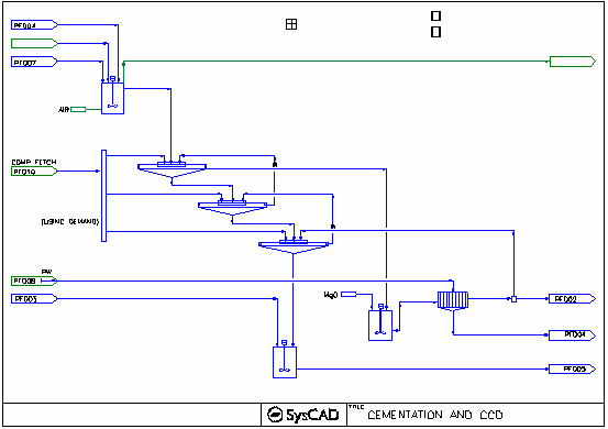
- The use of Demand (Flocculant to the CCD circuit) (Flowsheet 01 Cementation and CCD)
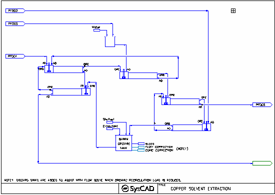
- Shows the setup of a solvent extraction circuit with a closed organic loop. (Flowsheet 02 Copper Solvent Extraction)
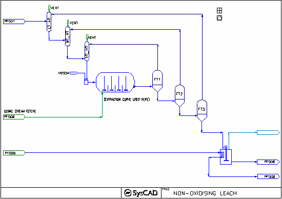
- The use of Model Procedures to add extraction based on residence time (Flowsheet 05 Non - Oxidizing Leach)
- Tank unit operation with Cooling water - using the Heat Exchanger element inside the tank. (Flowsheet 05 Non-oxidising Leach - Atmospheric_Tank)
- Heat of dilution (Flowsheet 05 Non-oxidising Leach - Acid Addition)
- Heat recovery (Flowsheets 05 and 07 non-oxidising and oxidising leach)
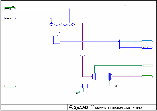
- The use of Multi-Stage Counter Flow Tie (Flowsheet 06 Copper Filtration and Dyring flowsheet)
- The use of Belt Filter (Flowsheet 06 Copper Filtration and Dyring flowsheet)
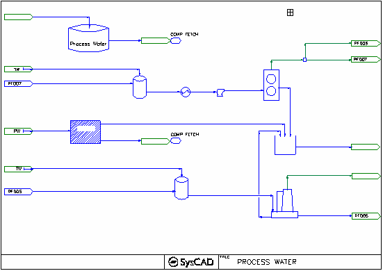
- The use of Reverse Osmosis (RO) Unit - for simple water treatment simulation (Flowsheet 08 Process Water Flowsheet).
- The use of Composition Fetch - e.g. Steam, Water, Floc, MgO Source. (Flowsheet 08 - Process water)
- The use of different Feeder Operation modes: Stream Fetch, Linked to MakeupSource, steam, vapour, liquid, Solid, Slurry.
- Various complex models can be simulated using the Tie/tank unit operation and General controller combination. (See Process Water flowsheet for examples)
- Sample Excel Reports
- Sample PGM and MP files
Brief Description
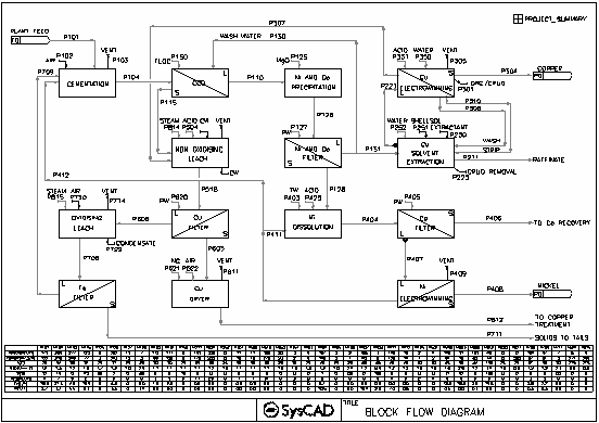
- This is a demonstration project of a simplified Nickel plant. The project contains 10 simplified flowsheets as follows:
- Cementation, CCD and Nickel/Cobalt precipitation
- Solvent Extraction circuit
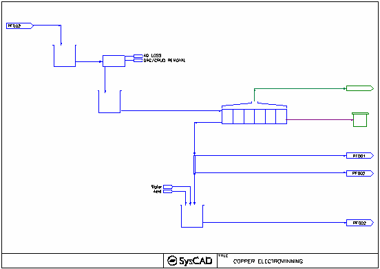
- Copper electrowinnig
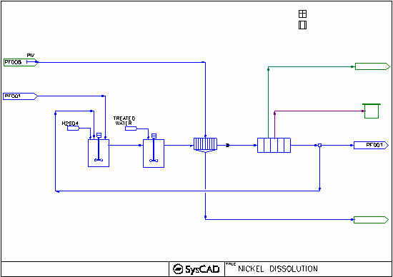
- Nickel dissolution and Recovery
- High Temperature non-oxidising leach with 3 flash stages
- Copper filter and dryer;
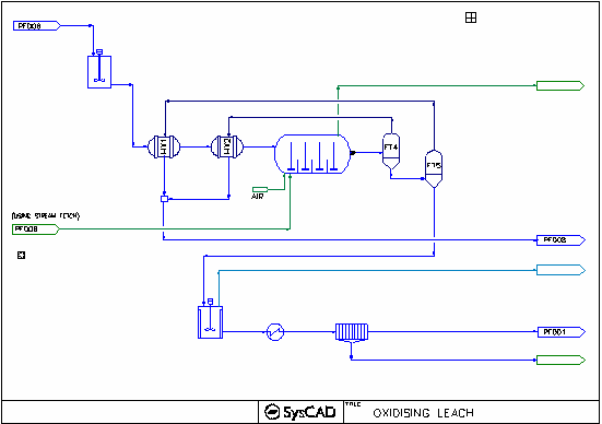
- Oxidising leach with 2 flash stages.
- Simplified process water page.
- Reagent Preparation page.
- Block Flow Diagram
Project Configuration
- Setting up Makeup Source and Makeup Block (MU)
- The main focus of this project is to show how to setup and consolidate all the reagent/utility usage in the plant.
- This is done by using makeup sources, there are five (5) Makeup Sources in this project, these are:
- Air_Source
- H2SO4_Source
- MgO_Source
- ProcessWater_Source
- TreatmentWater_Source
- Air and H2SO4 Sources can be found on the Reagents flowsheet, the configuration of these two sources are straight forward, where user define the source composition directly.
- The Process Water and Treatment Water sources found on the Process Water flowsheet are set up different, where source data is set to another process models. For example, the process water source is set up using composition fetch to obtain the same stream composition and condition as the Process water tank output (P801).
- The MgO Source Total usage is used by the MgO Feed Prep area to ensure sufficient amount of MgO slurry is made.
- Makeup Block (MU) sub model can be used in many process units, this includes the Tanks, Ties, Pipes, Feeder/XPG Connector and other select unit operations.
- Setting up the solvent extraction units
- Extraction_1 and Stripping_2 are using isotherm method to define the extraction / stripping of the Cu element.
- The OA ratio is set from the SX control.
- Setting up the closed organic loop
- The Barren Organic tank is set up with Makeup and Discard Blocks to help with flow and concentration correction.
- The organic flow is set by the OA ratio, as the flow changes, the makeup block will add more organic to increase the flow, or the discard block will discard material to reduce the flow.
- The extractant concentration is adjusted by the makeup and discard block using the same concept.
- Setting up the Electrolyte Filter
- This is set up as a tie model with discard sinks. Its purpose is to demonstrate how to discard two separate phases with varying amounts.
- Setting up extraction based on residence time
- Model procedure(MP) file is used in the Non_Oxidising_Leach Tank, where metal extraction will be based on the tank residence time.
- The MP file loads a predefined extraction table with time and extraction rate, SysCAD will read off this table of values and applied the correct extraction based on the current residence time of the tank.
- Setting up the belt filter
- Shows example data for Simple Filtration Washing Wash Loss curve.
- Setting up Dryer using Multi-Stage Counter Flow Tie
- The Dryer is set up as 3 stage (segment) counter current flow, where moist solid feed enters the cold end and the hot air enters at the hot end.
- Please note that the stage count starts at the Hot Gas End. See Multi-Stage Counter Flow Tie for more information.
- At each stage, user can set the Gas bypass percentage, this can be common to all stage or set per stage. Hot air bypass means some air is not used to exchange heat, therefore the Air out stream will be hotter.
- The solid and liquid lost to air stream percent is set a single stage only.
- Each stage is set up with Reaction sub model. So water evaporation can be spread out across the dryer segments.
- The Dryer is set up as 3 stage (segment) counter current flow, where moist solid feed enters the cold end and the hot air enters at the hot end.
- Setting up Reaction with material Source/Recycle
- The Autoclave2 unit uses a reaction block with Source and Recycle. The acid being produce in R2 is recycled back to be used by R1.
- Using Demand
- The floc circuit is set up with Demand + Stream Fetch
- The boiler circuit is set up with Demand + Linked to MakeupSource
- The cooling water circuit is set up with Demand + Linked to MakeupSource
Excel Report
- Example Plant Criteria Report, used to set data into SysCAD as well as reporting back the actual values from SysCAD. see also Project Criteria Report
- Example Stream Report, see also Example SysCAD Excel Reports
- Example Individual Flowsheets Report with Data Look-up, see also Flowsheet Report Example
- Example Overall Mass Balance and Water Balance Report, see also Example SysCAD Excel Reports
Example PGM and MP Files
- Various MP and PGM file examples are used in this project.
