Tank
Navigation: Models ➔ General Models ➔ Tank
| Tank | Tank - Dynamic Mode | Dynamic Tank - Optional Data Sections |
|---|
General Description
This page is for the Tank model when used in Steady State mode. For help on the Tank model in Dynamic mode, please see Tank - Dynamic Mode (there are significant differences in the tank behaviour between Steady State and Dynamic).
In Steady State, the tank model is very similar to the Tie model. When materials are mixed in the tank, a homogeneous product is produced.
Available Sub-Models
Evaluation Block:
- Makeup Blocks (one or more) may be enabled in a Tank. This allows the user to control the addition of streams such as reagents, water, air, etc. to the tank, often without having to use a PID or General controller.
- The Reaction Block (RB) allows the user to configure any number of reactions within the tank.
- The Environmental Heat Exchanger Block allows the user to add or remove energy from the tank using a number of different methods.
- The Evaporation Block allows the user to set the evaporation of either water only or a mixture of water and all other species that are specified as both liquid and vapour.
- The Vapour Liquid Equilibrium Block will attempt to ensure that the vapours and liquids of the selected species will be in equilibrium in the Tank. For example, if the equilibrium species is water and the tank is at atmospheric pressure, then SysCAD will maintain the temperature at, or below, the saturated temperature of 99.97°C by evaporating water if required.
- Discard Blocks (one or more) may be enabled in a Tank. This allows the user to control the discarding of material from the Tank, usually without having to use a PID or General controller.
Options:
- The General Model (GM) may be enabled in the tank in Steady State, allowing the user to control the split between the outgoing stream flows.
- The Thermal Split may also be enabled in Steady State IF the General Model is enabled. This option is used to adjust the temperatures of the outgoing streams from the unit.
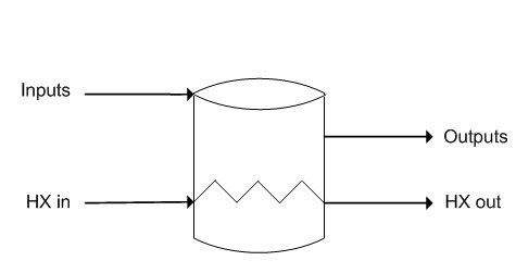
- The Heat Exchanger (HX) may be enabled. The user must also connect links to the HX input and the HX output. The Heat Exchange page needs to be configured with the relevant heat exchange area and overall heat transfer coefficient. The model combines all of the incoming streams, performs any reactions, and then carries out the heat exchange operation. Please note that the fluid in the heat exchanger will transfer energy via sensible heat ONLY. There is NO condensing or boiling in the heat exchanger.
Model Procedures
Model Procedures allows the user to implement code directly within the Tank.
To enable this, on the Info tab page tick the "Procedures" tickbox.
Diagram
The diagram shows a drawing of the tank, with a number of connecting streams. When the user inserts the tank into a flowsheet, a different graphics symbol can be selected from a pull down menu. The streams may be connected to any area of the drawing without affecting the actual connection point as SysCAD ignores the physical position of the connection. In dynamic mode, you can set the connection height of the links.
Inputs and Outputs
| Label | Required Optional |
Input Output |
Number of Connections | Description | |
| Min | Max | ||||
| Input | 1 Required | In | 1 | 30 | General purpose inlet (limit increased from 20 in Build 138.25939) |
| Output | 1 Required | Out | 1 | 20 | General purpose outlet |
| HX_in | Optional | In | 0/1* | 20 | Heat exchanger inlet (*only required if HX block is selected) (No condensing or evaporating allowed. See notes on options.) |
| HX_Out | Optional | Out | 0/1* | 20 | Heat exchanger outlet (*only required if HX block is selected) (No condensing or evaporating allowed. See notes on options.) |
Model Theory
In Steady State, all the input streams (excluding the HX streams) are perfectly mixed, then any sub-model actions occur on the mixture. This is very similar to the Tie model.
Flowchart
The following flowchart shows the sequence of events if any Evaluation Block sub-model options or the HX Block are enabled:
Data Sections
Summary of Data Sections
The tank access window may consist of a number of sections. This number may increase or decrease, based on user configuration and / or number of species.
- Tank-1 tab - Contains general information relating to the unit.
- PC - Optional tab that is visible if EB.Solubility.On and/or [email protected] is enabled on the first tab.
- MU - Optional tab, or multiple tabs if more than 1 Makeup is selected. Only visible if one of more Makeups are enabled in the Evaluation Block.
- RB - Optional tab, only visible if the Reactions are enabled in the Evaluation Block.
- HX - Optional tab, only visible if streams (in and out) have been connected to the Tank.HeatExchange IO connection ports.
- EHX - Optional tab, only visible if the EnvironHX is enabled in the Evaluation Block.
- Evap - Optional tab that is visible if Evaporator is enabled.
- VLE - Optional tab, only visible if the VLEquilibrium is enabled in the Evaluation Block.
- DB - Optional tab, or multiple tabs if more than 1 Discard Block is selected. Only visible if one of more Discard Blocks are enabled in the Evaluation Block.
- Split - Optional tab, only visible if SplitFlows is enabled.
- This tab is only available for Steady State mode.
- SplitT - Optional tab, only visible if SplitThermal is enabled.
- This may only be enabled after SplitFlow has been enabled.
- This tab is only available for Steady State mode.
- QFeed - Optional tab, only visible if ShowQFeed is enabled. This and subsequent tab pages, e.g. Sp, shows the properties of the mixed stream as the feed to the tank. If user has specified a required pressure in the tank, the mixed feed will be set to this pressure. This may cause the temperature of the mixture to change if the delta P is significantly different.
- This is before any Evaluation Block sub-models or the HX are evaluated.
- QProd - Optional tab, only visible if ShowQProd is enabled. This and subsequent tab pages, e.g. Sp, shows the properties of the mixed output stream as the product before separation to outlet streams of the tank.
- This is after any Evaluation Block sub-models or the HX are evaluated, but before flow splits.
- This tab is only available for Steady State mode.
- Info tab - Contains general settings for the unit and allows the user to include documentation about the unit and create Hyperlinks to external documents.
- MP tab - Optional tab, only visible if Procedures have been enabled on the Info tab page.
- Links tab, contains a summary table for all the input and output streams.
- Audit tab - Contains summary information required for Mass and Energy balance. See Model Examples for enthalpy calculation Examples.
- Additional fields are shown in Dynamic mode. These are described in the Tank - Dynamic Mode.
Tank Page
Unit Type: Tank-1 - The first tab page in the access window will have this name.
| Tag (Long/Short) | Input/ Calc | Description |
|---|---|---|
| Tag | Display | This name tag may be modified with the change tag option. |
| Condition | Display | OK if no errors/warnings, otherwise lists errors/warnings. |
| ConditionCount | Display | The current number of errors/warnings. If condition is OK, returns 0. |
| GeneralDescription / GenDesc | Display | This is an automatically generated description for the unit. If the user has entered text in the 'EqpDesc' field on the Info tab (see below), this will be displayed here. If this field is blank, then SysCAD will display the UnitType or SubClass. |
| Requirements | ||
| OperatingP - NOTE: this pressure is applied to the (combined) feed, before sub-models (if any). | ||
| Method | AutoDetect | If there are any liquids AND no vapours present in the feed, outlet streams will take the highest pressure of the feeds. Else (e.g. some vapours present) outlet streams will take the lowest pressure of the feeds. |
| LowestFeed | Outlet streams will take the lowest pressure of the feeds. | |
| HighestFeed | Outlet streams will take the highest pressure of the feeds. | |
| Atmospheric | Outlet streams will be at Atmospheric Pressure. The atmospheric pressure is calculated by SysCAD based on the user defined elevation (default elevation is at sea level = 101.325 kPa). The elevation can be changed on the Environment tab page of the Plant Model. | |
| RequiredP | Outlet streams will be at the user specified pressure. | |
| IgnoreLowMassFlow / IgnoreLowQm | Tick Box | This option is only visible if the AutoDetect, LowestFeed or HighestFeed methods are chosen. When calculating the outlet pressure and temperature of the tank, SysCAD will ignore the low flow feed streams should this option be selected. The low flow limit is set in the field below. |
| LowMassFlowFrac / LowQmFrac | Input | This field is only visible if the IgnoreLowQm option is selected. This is the amount any stream contributes to the total flow. For example, if the total feed to the tank is 10 kg/s, and this field is set to 1%. Then any feed streams with less than 0.1 kg/s will be ignored in the pressure calculations. |
| PressureReqd / P_Reqd | Input | This field is only visible if the RequiredP method is chosen. This is user specified pressure. |
| Result | Calc | The actual pressure used for the sum of the feeds which will also be the outlet pressure (unless further model options change the pressure). |
| ResTime (Residence Time) | ||
| Volume | Input | Only visible if the Calc option has been enabled. The operating volume of the unit. This will be used to calculate the apparent residence time in the unit. This is based on the volumetric flow of all outlets from the unit. |
| Slurry | Calc | Only visible if the Calc option has been enabled. The residence time of the slurry in the unit. |
| Total | Calc | Only visible if the Calc option has been enabled. The residence time for the slurry and the vapours in the unit. If there are any vapours leaving the unit, then this value will be smaller than the Slurry figure. |
| EB (Flow Evaluation Block) | ||
| Solubility.On | Tickbox | Only visible if Solubility has been defined for at least one species in the project. Allows the user to switch on any predefined solubility curve to adjust the composition of material in the unit. |
| [email protected] | Tickbox | Only visible if Phase Change at Temperature has been defined for at least one species in the project and Plant Model - Species Tab - PhaseChange@T = OFF. Allows the user to switch on any predefined phase changes at temperature in the unit. |
| EvalSequence | Calc | The sequence in which the sub models (which are part of the evaluation blocks) will be calculated. The sequence is determined by the priority selection for the individual sub-models. Note: If the user chooses On-AutoSequence then SysCAD will determine the sequence of the sub-models. The auto evaluation sequence followed will be the order the sub models are listed below. |
| Makeups | Input | The number of Makeup Blocks required. Extra dropdown options Makeup1, Makeup2, etc. will be added to allow these to be switched on and off and prioritised in relation to the other sub-models. |
| MakeupX | List | This can be used to switch the Makeup Block (MU) on or off and prioritise it in relation to the other sub-models. If this is 'On' then the associated page, MUX becomes visible and may be configured. Note: This field is only visible if the entry for 'Makeups' is greater than 0. If there is one makeup then X=1. If there are two makeups, then X=1 and X=2, etc. |
| Reactions | List | Reaction Block (RB) - Enable or disable Reactions and set the sequence in relation to the other sub-models. If this is 'On' then the associated page, RB becomes visible and may be configured. Note: The user does not have to configure a reaction file, even if this block is checked. |
| HeatXChg | List | This can be used to switch on the Heat Exchanger (HX). If this is 'On' then the associated page, HX becomes visible and may be configured. Note: The user does not have to configure the heat exchange, even if this block is checked. |
| EnvironHX | List | Environmental Heat Exchanger (EHX) - Enable or disable Environmental Heat Exchange and set the sequence in relation to the other sub-models. If this is 'On' then the associated page, EHX becomes visible and may be configured. Note: The user does not have to configure an environmental heat exchange, even if this block is checked. |
| Evaporation | List | Evaporation Block (Evap) - Enable or disable the Evaporator and set the sequence in relation to the other sub-models. If this is 'On' then the associated page, Evap becomes visible and may be configured. Note: The user does not have to configure an evaporator, even if this block is checked. |
| VLEquilibrium | List | Vapour Liquid Equilibrium (VLE) - Enable or disable Vapour Liquid Equilibrium and set the sequence in relation to the other sub-models. If this is 'On' then the associated page, VLE becomes visible and may be configured. Note: This option may automatically adjust the species make-up. |
| Discard | Input | The number of discard blocks required. Extra dropdown options Discard1, Discard2, etc. will be added to allow these to be switched on. |
| DiscardX | List | This can be used to switch the Discard Block (DB) on or off and prioritise it in relation to the other sub-models. If this is 'On' then the associated page, DBX becomes visible and may be configured. Note: This field is only visible if the entry for 'Discards' is greater than 0. If there is one discard then X=1. If there are two discards, then X=1 and X=2, etc. |
| Options | ||
| SplitFlows | Tick Box | This can be used to enable the Flow separate for output streams. If this box is checked then the associated page, Split, becomes visible and may be configured. Notes:
|
| SplitThermal | Tick Box | This option is only visible if the SplitFlows option has been chosen. This can be used to enable the uneven Energy distribution for output streams. If this box is checked then the associated page, SplitT, becomes visible and may be configured. Notes:
|
| ShowQFeed | Tick Box | QFeed and associated tab pages (e.g. Sp) will become visible, showing the properties of the combined feed stream. See Material Flow Section. This will be prior to any sub-model (e.g. reactions) actions. |
| ShowQProd | Tick Box | QProd and associated tab pages (e.g. Sp) will become visible, showing the properties of the products. See Material Flow Section. This will be after the actions of any sub-models and before any flow splits with the GM model. This option is not available in Dynamic mode. |
Split (Flow) Tab Page
The Split tab page can be used to specify how flow is distributed down stream.
| Tag (Long/Short) | Input/ Outputs | Description |
|---|---|---|
| GM ... | ||
| General Split Flows Model | ||
| Operation | General | Configure outgoing streams using mixture of methods. |
| Mass Frac | Split by mass fraction. | |
| Mass Flow | Specify mass flows. | |
| Volume Frac | Split by volume fraction. | |
| Volume Flow | Specify volume flows. | |
| Phase Mass Frac | Split each phase by mass fraction. | |
| Phase Mass Flow | Specify mass flows for each phase. | |
| Phase Volume Flow | Specify volume flows for each phase. | |
| Species Mass Frac | Split each species by mass fraction. | |
| Species Mass Flow | Specify mass flows for each species. | |
| Demand Mass Flow | Specify demand mass flows. | |
| Phase Recovery | Recover a fraction of a chosen phase to a particular stream. NOTE: This option is only available for models with only two output streams. | |
| Solids Recovery | Recover a fraction of solids to a particular stream. NOTE: This option is only available for models with only two output streams. | |
| Water Recovery | Recover a fraction of water to a particular stream. NOTE: This option is only available for models with only two output streams. | |
| Gas Vent | Recover a fraction of gases to a particular stream. NOTE: This option is only available for models with only two output streams. | |
| Target Stream | Available from Build 139.32925. Specify a single stream for all flow to exit by. | |
| Feed.MassFlow / Qm | Feedback | Available from Build 139.31388. The mass flow of the mixture before splitting of streams. |
| Feed.Temperature / T | Feedback | Available from Build 139.31388. The temperature of the mixture before splitting of streams - this is the temperature in the unit. |
OPERATION - General | ||
| ||
OPERATION - Mass Frac | ||
 |
| |
| Order | Display | The actual stream solving order of priority. |
| Priority | Drop list | Lets the user select the stream solving order. |
| Split | Input | Allows the user to specify the fraction of the total mass which is to be directed to this stream. |
OPERATION - Mass Flow | ||
 |
| |
| Order | Display | The actual stream solving order of priority. |
| Priority | List | Lets the user select the stream solving order. |
| Flow | Input | Allows the user to specify the mass flow of this stream. |
| Target | Tickbox | If this is ticked (On) then the user will NOT receive warning messages if the user specified requirements for this stream are not met, i.e. it is only a target. |
| QmErr | Display | Displays the difference between the mass flow specified by the user and the actual mass flow of the stream. |
OPERATION - Volume Frac | ||
 |
| |
OPERATION - Volume Flow | ||
 |
| |
| Order | Display | The actual stream solving order of priority. |
| Priority | Drop list | Lets the user select the stream solving order. |
| VFlow | Input | Allows the user to specify the volume flow of this stream. |
| Target | Tickbox | If this is ticked (On) then the user will NOT receive warning messages if the user specified requirements for this stream are not met, i.e. it is only a target. |
| QvErr | Display | Displays the difference between the volume flow specified by the user and the actual volume flow of the stream. |
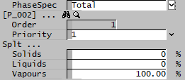
OPERATION - Phase Mass Frac | ||
 |
| |
| PhaseSpec | Drop List | Allows user to choose either Total phases (solids, liquids and vapours) or Individual phases. |
| Order | Display | The actual stream solving order of priority. |
| Priority | Drop list | Lets the user select the stream solving order. |
| If Total is chosen for the PhaseSpec, then the user will have the following fields for each stream: | ||
| Solids | Input | Allows the user to specify the mass fraction of the total solids which is to be directed to this stream. |
| Liquids | Input | Allows the user to specify the mass fraction of the total liquids which is to be directed to this stream. |
| Vapours | Input | Allows the user to specify the mass fraction of the total gases which is to be directed to this stream. |
| If Individual is chosen for the PhaseSpec, then the fields will be the same except instead of Solids, Liquids and Vapours, the user will be able to specify fractions for each individual phase defined in the project (for example, aq (aqueous), o (organic), sl (slag), etc.). | ||
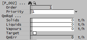
OPERATION - Phase Mass Flow | ||
 |
| |
| Order | Display | The actual stream solving order of priority. |
| Priority | Drop list | Lets the user select the stream solving order. |
| Solids | Input | Allows the user to specify the mass flow of solids in this stream. |
| Liquids | Input | Allows the user to specify the mass flow of liquids in this stream. |
| Vapours | Input | Allows the user to specify the mass flow of gases in this stream. |
| Target | Tickbox | If this is ticked (On) then the user will NOT receive warning messages if the user specified requirements for this stream are not met, i.e. they are only targets. |
| QmErr | Display | Displays the difference between the total mass flow specified by the user (sum of all three phases) and the actual total mass flow of the stream. |
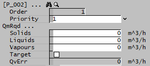
OPERATION - Phase Volume Flow | ||
 |
| |
OPERATION - Species Mass Frac | ||
 |
| |
OPERATION - Species Mass Flow | ||
 |
| |
OPERATION - Demand Mass Flow | ||
 |
| |
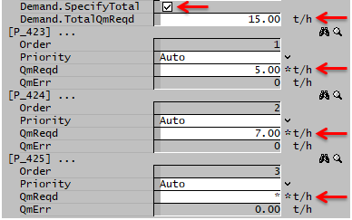
| Demand.SpecifyTotal | Tick Box | This option allows the user to specify the Total Demand mass flow and up to n-1 individual stream flows. When the Total flow is specified, at least one stream needs to be * (unspecified). When not used, all n individual output stream flows must be specified. |
| Demand.TotalQmReqd | Input | Only visible if Demand.SpecifyTotal option is selected. Allows the user to input the total Demand flow. |
| Demand.TotalQmErr | Display | Available from Build 139.32925. Only visible if Demand.SpecifyTotal option is selected. Displays the flowrate error between the total demand and the current feed flowrate. |
| Order | Display | The actual stream solving order of priority. |
| Priority | List | Lets the user select the stream solving order. |
| QmReqd | Input | Allows the user to specify the Demand mass flow to this stream. Enter * (unspecified) for the balance stream(s) when using Demand.SpecifyTotal. |
| QmErr | Display | Displays the difference between the Demand mass flow specified by the user and the actual mass flow of the stream. |
OPERATION - Phase Recovery | ||
 |
| |
| Phase | Drop List | The phase to be recovered (solid, liquid or gas) |
| Stream | Drop List | The stream which the user wishes to specify the fraction and composition. |
| Fraction | Input | The (mass) fraction of the chosen phase which will be sent to the chosen stream. In the above example, we are sending 90% of the feed solids to the specified Stream. |
| Composition | Input | The (mass) fraction of the chosen phase in the chosen stream. The fractions of the other phases (other than the phase to be recovered) will be automatically adjusted in order to achieve this composition. In the above example, we are requesting the chosen stream to be 80% solids. |
OPERATION - Solids Recovery | ||
 |
| |
| Stream | Drop List | The stream which the user wishes to specify the fraction and composition. |
| Fraction | Input | The (mass) fraction of the solid phase which will be sent to the chosen stream. In the above example, we are sending 50% of the feed solids to the specified Stream. |
| Composition | Input | The (mass) fraction of the solid phase in the chosen stream. The fractions of the other phases (other than the solid phase) will be automatically adjusted in order to achieve this composition. In the above example, we are requesting the chosen stream to be 65% solids. |
OPERATION - Water Recovery | ||
 |
| |
| ProductStream / Stream | Drop List | The stream which the user wishes to represent the clean water stream. (The other stream will be the brine) |
| Yield | Input | The (mass) fraction of water to be recovered. In the above example, we are sending 75% of the feed water to the Product Stream. |
| Efficiency | Input | The (mass) fraction of other liquid compounds removed. In the above example, we are requesting 95% of all other liquid compounds in the feed be removed and sent to the brine. That means, 5% of other liquid compounds present in the feed will be in the water product stream. |
OPERATION - Gas Vent | ||
| ||
| VentStream / Stream | Drop List | The stream which the user wishes to represent the vent stream. |
| Fraction | Input | The (mass) fraction of all gases in the feed to be sent to the vent. In the above example, we are sending 90% of the feed gaseous compounds to the specified Stream. |
OPERATION - Target Stream | ||
 |
| |
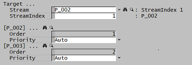
| Stream | Drop List | The stream which the user wishes to send all flow to. Can also be changed via StreamIndex. |
| StreamIndex | Input | The index of the stream which the user wishes to send all flow to. The index of each stream is based on the priority setting for each stream. Can also be changed via Stream droplist. |
| Order | Display | The actual stream index. |
| Priority | Drop list | Lets the user select the stream index for each outlet stream. |
Split Thermal Tab Page
The Split Thermal (SplitT) tab page can be used to specify how heat is distributed with the streams.
| Tag (Long/Short) | Input/Calc | Description |
|---|---|---|
| Mixture temperature before thermal split | ||
| Feed.MassFlow / Qm | Feedback | Only available in Build 139.31388 or later. The mass flow of the mixture before splitting of streams. |
| Feed.Temperature / T | Feedback | The temperature of the mixture before splitting of streams - this is the temperature in the unit. |
| Condition | Feedback | OK if no errors, otherwise displays error message. |
| AllowHX | Tickbox | Selecting this option allows the user to specify temperatures for all outgoing streams. SysCAD will add or remove energy to conserve the energy across the unit operation. Any energy added/removed will be shown on the HeatFlow field. |
| UseSplitFlowsPriority | Tickbox | Only available in Build 139.31424 or later. If selected, the order of streams on the SplitT page will match the order on the Split page. If not selected, then the user will be able to set the priorities for each stream on the SplitT page, independent of the order on the Split page. |
| HeatFlow | FeedBack | In older builds, this was only visible when the AllowHX option had been enabled. This shows the amount of energy added or removed in order to achieve the temperatures specified by the user. |
| HeatCorrection | FeedBack | Only available in Build 139.31388 or later. Only visible when the AllowHX option has NOT been enabled. This shows the amount of energy that would need to be added or removed in order to achieve the temperatures specified by the user. This will only be non-zero if the required temperatures can not be achieved. |
| TIOs.[stream name]... | ||
| Order | FeedBack | This can be changed using the Priority field (if available). |
| Priority | List | This is used to change the order of the output streams if the Required or Change modes are selected. In Build 139.31388 or later, it is only available if the UseSplitFlowsPriority option has NOT been enabled. |
| Mode (See Options and Examples for more info) |
Required | The user may specify the required temperature of the outlet stream. This temperature may be limited by the temperature change limits specified. |
| Change | The user may specify the required temperature change for the outlet stream. This temperature may be limited by the temperature change limits specified. | |
| FreeDiff | The user can set a temperature difference for the selected outlet stream to the streams that are set at Free. For example, if the unit operation has two outlet streams, stream 1 is set at FreeDiff = 10, stream 2 is set at Free, then Stream 1 will be 10 degrees hotter than stream 2 when solved. This temperature may be limited by the temperature change limits specified. | |
| Free | The user may not specify any outlet temperature requirements, SysCAD will determine the outlet temperature. If Free is used for all streams then all streams will have the same outlet temperature (same behaviour as when SplitT model is not used at all). | |
| TemperatureReqd / T_Reqd | Input | This is visible with mode set to Required, use this to specify the stream outlet temperature. |
| TempChange | Input | This is visible with mode set to Change, use this to specify the stream outlet temperature change. |
| TempDiff | Input | This is visible with mode set to FreeDiff, use this to specify the stream outlet temperature difference for the current stream and the streams that are set at Free. |
| TemperatureOut / To | FeedBack | This is the outlet temperature for the stream. |
| Result | FeedBack | This shows whether the user specified temperature conditions have been achieved. NOTE: Fraction of the target is based on required temperature change that has been achieved. |
| Achieved | FeedBack | This shows the fraction of the required temperature change that has been achieved. |
| MassFlow / Qm | Feedback | Only available in Build 139.31388 or later. The mass flow of the stream, after the split logic has been applied. |
| Temperature change limits: | ||
| FinalT.Min | Input | The minimum temperature of the mixture leaving the unit operation. If the balance stream temperature falls below this minimum when the AllowHX option is ticked, heat will be added to make it up to the minimum temperature. If AllowHX option is not selected, all outlet stream temperatures will be adjusted to keep a balance of heat. |
| FinalT.Max | Input | The maximum temperature of the mixture leaving the unit operation. If the balance stream temperature is above this maximum when the AllowHX option is ticked, heat will be removed to limit it to the maximum temperature. If AllowHX option is not selected, all outlet stream temperatures will be adjusted to keep a balance of heat. |
| ChangeT.Limit | Tickbox | Selecting this option allows the user to specify temperature limits for all outgoing streams. If AllowHX option is selected, SysCAD will add or remove heat to conserve the energy across the unit operation. Any energy added/removed will be shown on the PowerInput field. |
| ChangeT.MaxDrop | Input | Only visible if ChangeT.Limit is enabled. This is the maximum amount that any stream be below the Feed temperature of the SplitT block. |
| ChangeT.MaxRise | Input | Only visible if ChangeT.Limit is enabled. This is the maximum amount that any stream be above the Feed temperature of the SplitT block. |
Dynamic Mode Data Sections
The fields which appear in the access window for the tank in Dynamic mode only are shown in Tank - Dynamic Mode.
Adding this Model to a Project
Add to Configuration File
Sort either by DLL or Group:
| DLL: | Basic1.dll |
→ | Units/Links | → | Process: Tank(1) | |
| or | Group: | General |
→ | Units/Links | → | Process: Tank(1) |
See Model Selection for more information on adding models to the configuration file.
Insert into Project Flowsheet
| Insert Unit | → | Process | → | Tank(1) |
See Insert Unit for general information on inserting units.
Hints and Comments
- If the user configures the GM, and then at a later stage adds or removes a stream (input or output), this may have an impact on the GM configuration. It is recommended that the user check the GM every time a stream change is made.
- In Steady State, the Tie model is almost identical to the tank model, except that the Tie does not have the Heat Exchanger (HX) sub-model.
- In Steady State, the tank model can be used with Demand.
- There may be mass entering or leaving the tank via the Reaction Block source or sink, so if the outgoing mass is not the same as the incoming mass, this may be a place to check first.
- If the user 'Resets' or uses the 'Empty Process' SetState option, then all connecting flanges will also be set to zero flow.
- If the user defined pressure is very different to the feed stream pressure, then this may cause the temperature change to be quite significant. If the inlet temperature is already high, then it is possible for the temperature to go above the critical temperature of water. In this case, the unit will return an energy imbalance error message. To avoid this issue, please consider using the Flash Tank so that VLE, T and P can be solved simultaneously in an iterative process.
