Example - 03UnitModels Projects 1
Navigation: User Guide ➔ Example Projects ➔ 03 UnitModels (Part 1)
Related Links: 03 UnitModels (Part 2)
Absorption Tower (MultiK) Project
Project Location
This is a Steady State project available from Build 139.33457 and is stored at:
..\SysCADXXX\Examples\03 UnitModels\Absorption Tower (MultiK).spf
Features Demonstrated
- A simple project showing how to emulate a column using:
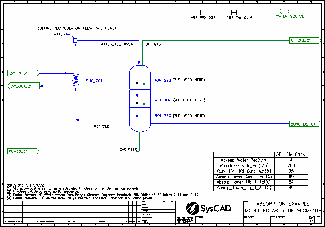
- Flowsheet 01: Three sections with the Tie unit operation.
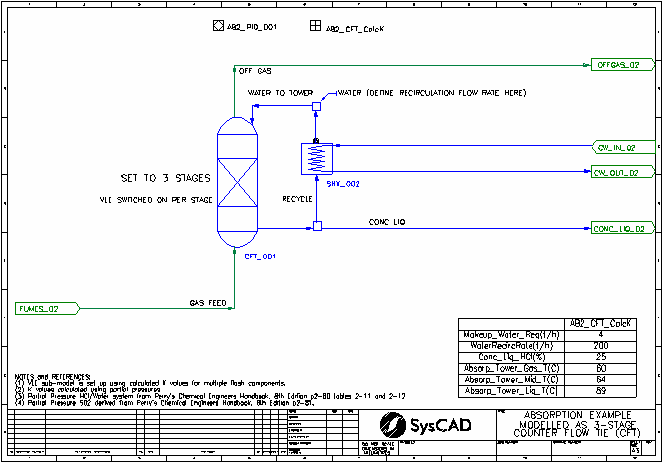
- Flowsheet 02: Flexible number of sections with the Counter Flow Tie unit operation.
- Shows the use Multi-component VLE.
- Shows the use of Simple Heat Exchanger
- Shows the use of Multi-Stage Counter Flow Tie
- Shows the use of Makeup Source for setting the re-circulation flow.
- Shows the use of PID Controller
- Shows the use of General Controller for calculations, including use of user defined Class and Matrix Class.
Brief Project Description
This project shows how to use simple process units to model complex systems. The Project has two flowsheets, the first one showing the absorption tower modelled as three sections and the second flowsheet showing the absorption tower modelled as a 3 stage Counter Flow Tie unit operation.
- Absorption tower: Uses multi-component VLE to remove HCl and SO2 from fumes.
- Simple Heat Exchanger provides the cooling required.
Project Configuration
- Partial Pressure Data
- The partial pressure data for HCl and SO2 are defined in matrices in PGM files.
- This data is used in the General Controllers to calculate the K values used in the Multi-component VLE calculations.
- Absorption Tower:
- Modelled using three simple Ties with Multi-component VLE (using user calculated K values) and SplitFlow sub-models.
- Modelled using counter flow tie with Multi-component VLE (using user calculated K values) sub-model. With this setup, user can freely change the number of stages without having to change the flowsheet.
- General Controller uses a user defined Class to calculate the relevant K values for HCl, H2O, SO2 and CO2 for each stage.
- User defines the concentration leaving the tower bottom, the recycle is manipulated by PID Controller to achieve this concentration.
- Makeup water is added to maintain a predefined re-circulation rate.
- Cooling water is added by PID Controller to maintain a user defined absorption gas outlet temperature.
Absorption Tower Example Project
Project Location
This is a Steady State project and is stored at:
..\SysCADXXX\Examples\03 UnitModels\Absorption Tower Example.spf
Features Demonstrated
- A simple project showing how to emulate a column using:
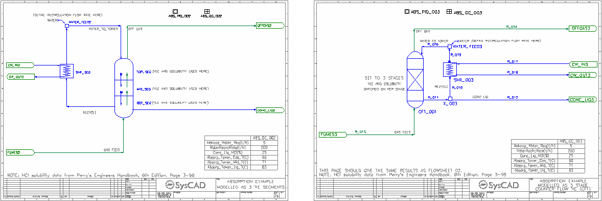
- Flowsheet 01: two sections with the Tie unit operation.
- Flowsheet 02: three sections with the Tie unit operation.
- Flowsheet 03: Flexible number of sections with the Counter Flow Tie unit operation.
- Shows the use VLE.
- Shows the use Solubility
- Shows the use of Simple Heat Exchanger
- Shows the use of Multi-Stage Counter Flow Tie
- Shows the use of Makeup Source for setting the re-circulation flow.
- Shows the use of PID Controller
- Shows the use of General Controller for side calculation.
Brief Project Description
This project shows how to use simple process units to model complex systems. The Project has three flowsheets, first one showing the absorption tower modelled as two sections, the second one modelled as three sections and the last flowsheet showing the absorption tower modelled as the 3 stage Counter Flow Tie unit operation.
- Absorption tower: Uses solubility and VLE to remove HCl from fumes.
- Simple Heat Exchanger provides the cooling required.
Project Configuration
- Solubility Data
- Define the solubility data in the species database
- Once this is done, user can turn on the solubility Globally or on per unit operation basis. In this example, it is turned on per unit operation.
- Absorption Tower:
- Modelled using two / three simple Ties with VLE / Solubility / SplitFlow sub-models.
- Modelled using counter flow tie with VLE / Solubility sub-models. With this setup, user can freely change the number of stages without having to change the flowsheet.
- User defines the concentration leaving the tower bottom, the recycle is manipulated to achieve this concentration.
- Makeup water is added to maintain a predefined re-circulation rate.
- Cooling water is added to maintain a user defined absorption gas outlet temperature.
Boiler & Combustion Project
Project Location
This is a Steady State project and is stored at:
..\SysCADXXX\Examples\03 UnitModels\Boiler and Combustion Example.spf
Features Demonstrated
- A simple project showing how to calculate the heat energy required for the Boiler.
- Shows the use of a Tank with reactions - Combustion reactions.
- Shows the use of Hot Flash Tie
- Shows the use of Simple Heat Exchanger
- Shows the use of Set Tag Controller
- Shows the use of PID Controller
- Shows the use of PGM file for side calculation.
- Shows the use of EHX as a method of stabilising the solution.
Brief Project Description
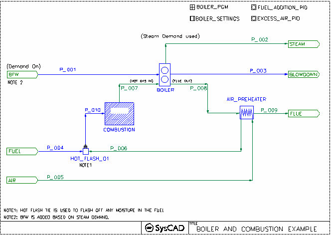
This project shows how to use simple process units to model complex systems. The Project is set up as two separate sections, Boiler and Combustion.
- Boiler: The boiler section will heat and vapourise the boiler feed water, producing steam at the defined conditions. It will also report the energy required to achieve this.
- Combustion: Fuel is used to produce energy in the combustion chamber, the amount of energy produced is dictated by the boiler.
- Air to the combustion chamber is preheated by heat exchange with the flue gas. Air supply is in excess, done via a PID controller.
Project Configuration
- Boiler Section:
- User specifies the BFW condition (in the feeder)
- User defines the Final T&P, Blowdown % and boiler efficiency
- SysCAD calculates the heat required for boiling and superheating the steam
- SysCAD calculated the fuel energy requirements based on boiler efficiency. This energy is tells the combustion chamber how much heat is required.
- Fuel Section:
- When Preheated Air is combined with the Fuel, any moisture present is evaporated, this is done in the Hot Flash Tie.
- The total combustion reaction energy should be equal to the required fuel energy calculated by the boiler.
- A PID controller measures this and adjusts the Fuel input to achieve the required energy. (This is coupled with a EHX sub-model on Flue out stream to stabilise the solution.)
- Energy is removed from the combustion outlet stream by the boiler.
- The hot flue gas is then used to preheat the air to the combustion chamber.
Calcine & Fuel Project
Project Location
This is a Steady State project and is stored at:
..\SysCADXXX\Examples\03 UnitModels\Calcine and Fuel Example.spf
Features Demonstrated
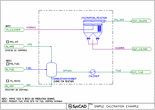
- A simple project showing how to calculate the heat energy required for the Calciner.
- Shows the use of Tanks with reactions - Calcination and Combustion reactions.
- Shows the use of Simple Heater
- Shows the use of FEM Reactor
- Shows the use of PID controller
- Shows the use of PGM file for side calculation.
- Shows the use of EHX to set various heat sinks.
Brief Project Description
- The Project is set up as two separate sections, Calciner and Combustion. The temperature of the calcined alumina is interlocked with the fuel addition.
- Combustion: The energy from the actual combustion reactions emulates the energy required by the Calciner to heat up the mixture.
Project Configuration
- Calciner
- Reactions are used to dry the mixture
- Reaction block Heat Exchange Final Temperature option is used to bring the Product temperature to the required amount.
- SplitFlow is used to separate the gas and solids
- Combustion Section
- Combustion reactions are used to produce the amount of heat required by the calciner.
- Excess Air is used, Air addition controlled via PID.
- The usage of two air inlets can be done in such a way that the first air inlet will provide the stoichiometric amount of oxygen to the combustion chamber, while the second inlet is adjust to give the required % of excess air. (This is not demonstrated in the example project)
Crystallisation Project
Project Location
This is a Steady State project and is stored at:
..\SysCADXXX\Examples\03 Unit Models\Crystallisation Example.spf
Features Demonstrated
- Solubility changes in a project as a function of temperature;
- A single aqueous species has a number of solubility curves, with different solid species.
- Use of Evaporator model as a Crystalliser, with Embedded Heater.
- Other Solubility Example Projects: Solubility Example, Absorption Tower Example Project, Evaporator Flash Train Project, Mechanical Vapour Recompression MVR Example
Brief Description
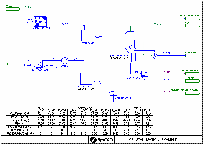
This is a simple project to show how a single aqueous species may have multiple solubility curves and may also have curves with different solid species. The solubility functionality is enabled in individual units.
- A stream containing Na2SO4(aq) is chilled and the solubility curve for Na2SO4(aq):Na2SO4.10H2O(s) is enabled in Crystalliser 1. The solution is saturated with respect to Na2SO4.10H2O(s), and hence this solid precipitates.
- The liquor from Crystalliser 1 is heated and ammonium sulfate (amsul) is removed.
- The solution from the amsul removal is sent to a 2nd crystalliser, where it is heated under vacuum. The solution is saturated with respect to Na2SO4(s).
- The solution from Crystalliser 2 is sent to a centrifuge where the Na2SO4(s) crystals are removed.
Project Configuration
- Defining and Enabling Solubility
- Adding solubility data to the Species database.
- Enable Solubility in individual units using the Solubility.On functionality.
- Viewing Solubility Data
- Enable different solubility information on View | PlantModel | Soluble.
- The Solubility data can be found on Pipes, under Qo.Soluble section.
- For units in which the solubility functionality is enabled, the data can be viewed on the PC Tab.
HP Autoclave Leach Project
Project Location
..\SysCADXXX\Examples\03 UnitModels\High Pressure Autoclave Leach Example.spf
Features Demonstrated
- Sulphuric acid heat of dilution and phase change are demonstrated in the acid mixer via the reaction block.
- Typical Base metal leach reactions are in place in the High Pressure Autoclave.
- Shows the use of Reaction Source & Recycle
- Using show species requirements to calculate reagent usage. See Example - Using Show Species Requirements
- Ratio control is used when adding flocculant to the thickener. This is done via the General Control (PGM file).
- Acid and Steam additions are controlled via the PID controllers.
- Example reporting file can also be found in the project - Report.xls.
Brief Description
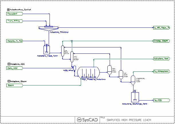
- This is a simple project demonstrating a very simplified High Pressure Leach Circuit, where the slurry is leached with acid at High Temperature.
- The leached slurry is then cooled in multistage flashing
- The flash vapour is re-used to preheat the autoclave feed.
Project Configuration
- Acid Mixer - Heat of dilution occurs in this vessel, compare the QFeed Temperature with QProd Temperature.
- Autoclave
- User must specify a pressure for this unit. The pressure should be high enough to cover temperature changes and allow for non-condensables.
- VLEquilibrium is switched on to condense the steam added to the autoclave.
- Reactions block is used to specify various base metal leach reactions.
Specifying the Reactions:
- All reactions are in sequential order (this is important).
- Looking at the reaction file, H2SO4 is consumed by a number of reactions with lower sequence numbers and then generated by some reactions with higher sequence numbers. When reactions are evaluated in sequence, normally products produced by later reactions would not be used by earlier reactions, this will lead to incorrect acid usage values.
- To overcome this problem, we have added a H2SO4 reaction Source (in addition to the actual Conc Acid feed stream.) This H2SO4 reaction source will tell SysCAD to use up the acid generated by later reactions (shown as recycle amount).
- For more information, please see Reaction Source & Recycle.
Included Excel Report
Report.XLS - this excel report show some basic report formats for the project, these include Input Criteria, reaction and Stream data report.
IX Column Uranium Example
Project Location
..\SysCADXXX\Examples\03 UnitModels\IX Column Uranium Example.spf
Features Demonstrated
How to simulate the Ion Exchange Column using SysCAD.
Brief Project Description
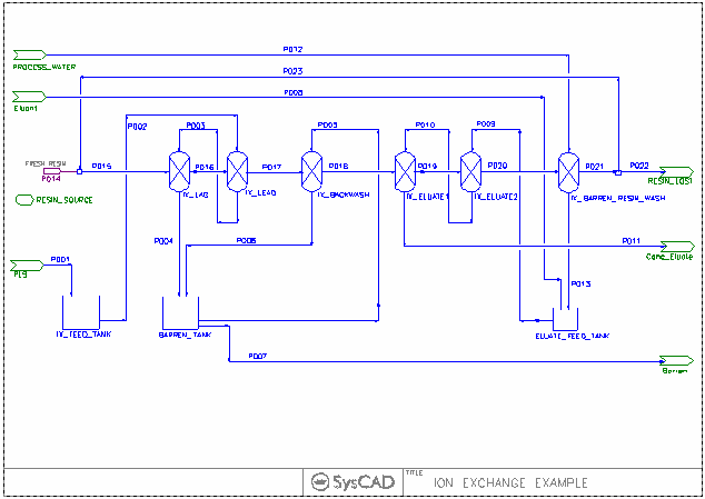
This is a steady state simulation of a dynamic batch process. To do that we need to separate out the individual batch steps and model them as individual unit operations. In this model we follow the resin through the process flow diagram. As the resin moves through the process steps, it sees the same solutions in the same order that it would see if it were in a fixed place in a column during a batch process cycle (the resin is fixed in the column and different solutions are passed over it). This will give the same results for the flows out of the column as averaging the flows of a true batch process over time. While there are some limitations in what can be modeled in steady state, it does give a good representation of how this IX unit interacts with a full plant flow sheet and also gives an accurate mass balance.
- The Ion Exchange column is simulated in six sections, each section is simulated using the IonExchange model.
- The resin will travel through all the sections as it is regenerated and recycled.
- Resin moves through two columns (lag and lead) as it is loaded with uranium. The lead column is then backwashed to remove any fines from the loading process. The resin is then transferred to the second stage of elution, followed by the first stage of elution. After first stage elution, the resin is barren and is washed to remove any residual eluant solution in barren resin wash.
- Each column represents either a physical column (such as lead/lag loading columns and the two elution columns) or a stage in the process (such as backwashing and barren resin wash).
- Resin bleed is done via the resin lost stream.
- The resin recirculation flow is topped up via Makeup source.
Project Configuration
- All sections will have the same resin flow setting
- Reactions blocks are used where needed to emulate the loading and regeneration of resin.
- Resin bleed stream is important to avoid continuous build up of impurities in the resin stream.
Included Excel Report
IX Column Uranium Example.XLS - this excel report show some basic report formats for the project, these include Input Criteria, reaction and Stream data report.
