Ion Exchange
Navigation: Models ➔ Mass Separation Models ➔ Ion Exchange
General Description
The Ion Exchange (IX) column unit model is used to simulate the movement of liquor through a solid phase of resin. When implemented as part of an ion exchange circuit, the resin and interstitial liquid (IL) is carried between the batch stages as a simulated moving bed.
The unit operates as a plug flow column, with the original interstitial liquids being discharged before the incoming liquor, without any mixing. Optional IL connections allow the plug flow sequence of interstitial liquids to be preserved between stages - this is generally required only when a stage has insufficient feed liquor flow to displace all of the original IL.
Two liquor discharge connections are provided for the first and second discharge. Original interstitial liquids (whether from feed resin or IL connection) are first discharged into Liq1Out, then any overfill of feed Liquor is discharged into Liq2Out (or mixed with Liq1Out if not connected).
Reactions may be defined between incoming Liquor and solid Resin. Thermal override may be used to set the temperature of discharge streams to a fixed value or offset from the incoming resin temperature.
Diagram

The diagram shows a drawing of the Ion Exchange Column with all connectable streams of the unit. The physical location of the streams connecting to the unit is unimportant. The user may connect the streams to any position on the unit.
Inputs and Outputs
| Label | Required Optional |
Input Output |
Number of Connections | Description | |
| Min | Max | ||||
| Liquor | Required | In | 1 | 5 | The incoming process liquor stream which will displace the original interstitial liquids and may react with the resin. This stream should not contain any solids. |
| Resin | Required | In | 1 | 10 | The effective resin flow of the simulated moving bed, typically 1 bed volume equivalent. Contains solid resin and its interstitial liquid. If the IL stream is also connected, then the interstitial liquid in this stream is furthest from the column outlet. Required connection from Build 139.37009. |
| IL | Optional | In | 0 | 5 | The interstitial liquid closest to the column outlet (i.e. the first to be discharged). This is an optional stream to preserve the plug flow state of the IL in the column. |
| ResinOut | Required | Out | 1 | 1 | The effective resin outlet flow of the simulated moving bed. Contains all solids and the new interstitial liquid which remains associated with the resin. |
| Liquor1Out | Required | Out | 1 | 1 | The first column discharge. Contains displaced interstitial liquids which were originally in the column, as well as any excess IL from the feed (>Liquid Bed Volume). Required connection from Build 139.37009. |
| Liquor2Out | Optional | Out | 0 | 1 | The second column discharge. Contains excess/overfilled feed liquor which has passed through the column after all original interstitial liquids have been discharged. |
| ILOut | Optional | Out | 0 | 1 | Any original interstitial liquid that has not been displaced from the column by Liquor. This is an optional stream to preserve the plug flow state of the IL in the column. |
| Vent | Optional | Out | 0 | 1 | Any gases fed to the unit or produced inside the unit. |
The following logic is applied if the optional outlet connections are not made:
From Build 139.37009:
Label If not connected send to Liquor2Out Liquor1Out ILOut ResinOut Vent Liquor1Out
Before Build 139.37009 (when Liquor1Out was optional):
Label If not connected send to Otherwise send to Liquor1Out Liquor2Out ResinOut Liquor2Out Liquor1Out ResinOut ILOut ResinOut N/A Vent Liquor1Out ResinOut
Behaviour when Model is OFF
If the unit is disabled by unticking the On tick box, then the following actions occur:
- No reactions will occur.
From Build 139.37009:
- The Resin input stream will flow straight out of the ResinOut outlet.
- The IL input stream will flow straight out of the ILOut outlet. If ILOut is not connected, then it will be mixed with the ResinOut outlet.
- The Liquor input stream will flow straight out of the Liquor2Out outlet. If Liquor2Out is not connected, then it will flow straight out of the Liquor1Out outlet.
Before Build 139.37009:
- All input streams will be mixed and flow out of the ResinOut outlet, including any liquors and vapours.
Block Flow Diagram
The following diagram shows the basic solid and liquid flows of the model if all connections are made.

Model Theory
Simulated Moving Bed
In reality, the solid resin does not flow as is it contained within the column. To model this batch process in a steady state model, the resin is modelled as a simulated moving bed. Resin and interstitial liquids "flow" between different columns representing the different batch stages of the IX process (Loading, Elution, Washing, Regeneration, etc.).
As such, the bed volumes (BVs) are defined as volumetric flowrates, not physical volumes. The resin flowrate represents one equivalent bed volume proportional to the liquor charge. For example: if a batch stage requires 5 BV of liquor fed to the column, then the ratio of Liquor to Resin should be 5:1. (This may be on a solid, liquid, or total BV basis, depending on plant-specific nomenclature.)
Given this is a batch process modelled in steady state, it is important to note that the instantaneous flowrates of liquor are not factored into the calculation - only the relative flowrates are important. Often the system can be scaled to match one continuous flow in the system.
Ideally, resin from the final stage should loop back to the first stage. Where there are resin solid losses or a purge stream, this can be controlled with a resin feed or makeup. If there are no losses, this can be configured with a Composition Fetch (to avoid the infinite solutions of a closed loop with no inputs/outputs).
Plug Flow
The liquid BV (BV.ILVolFlow, or ResinOut.LQvReqd before Build 139.37009) associated with the solid BV (BV.ResinVolFlow) is based on an interstitial liquid factor (ILFactor) or fraction (ILFraction). This volume includes the interstitial volume supported by the resin plus any space in the column between the resin meshes and control valves.
Solid Volume Basis (user input or measured from Resin feed):
- Resin Solid Volume Flow * ILFactor = Interstitial Liquid Volume Flow
Total Volume Basis (user input, from Build 139.37009):
- Total Volume Flow * ILFraction = Interstitial Liquid Volume Flow
- Total Volume Flow * (1 - ILFraction) = Resin Solid Volume Flow
The Interstitial Liquid Volume Flow may be separated into V1 and V2, where:
- V1 is the volume of liquor closest to the discharge outlet (IL in/out, if connected)
- V2 is the volume of liquid furthest from the discharge outlet (liquid with Resin in/out)
- These are discharged in order - first from V1, then from V2.
- If the IL or Resin feed flows contain too much liquid, these are immediately discharged to Liquor1Out.
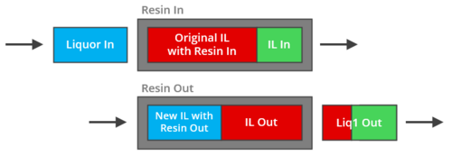
High Liquor Flow
The flow of Liquor will typically be larger than IL BV, displacing all original IL in the column. As such, all original IL (V1 + V2) is discharged to Liquor1Out without mixing with the incoming Liquor. Then, any excess/overfill of Liquor reports to Liquor2Out (or if not connected, mixed with Liquor1Out). The Resin outlet then contains new interstitial liquid equal to the Interstitial Liquid Volume Flow, made up of Liquor.
For example, eluding a red IL with blue Liquor, ILFactor = 0.85:
Material Resin Liquor Liquor1Out Liquor2Out ResinOut Resin(s) (m3/h) 10 0 0 0 10 Red(l) (m3/h) 8.5 0 8.5 0 0 Blue(l) (m3/h) 0 12 0 3.5 8.5

Low Liquor Flow
In cases where there is not enough Liquor to displace all original IL (Liquor Flow < IL BV), there will be a portion of original IL remaining in the column after discharge to Liquor1Out. Any residual IL is mixed (V1 + V2, if applicable) and reports to ILOut to preserve the plug flow state (if not connected, mixed with the Resin and the plug flow state is lost). The remaining Interstitial Liquid Volume Flow is made up of Liquor and leaves with the Resin.
For example, eluding red and green ILs (green closer to discharge) with blue Liquor, ILFactor = 0.85:
Material Resin IL Liquor Liquor1Out ILOut ResinOut Resin(s) (m3/h) 10 0 0 0 0 10 Red(l) (m3/h) 5.5 0 0 2 3.5 0 Green(l) (m3/h) 0 3 0 3 0 0 Blue(l) (m3/h) 0 0 5 0 0 5
NOTE: IL In is only required if the previous stage has an IL Out. Either scenario above could include or exclude IL In.
- In the high flow case with IL In, this liquor would be discharged and mixed with Liquor1 Out.
- In the low flow case without IL In, Liquor1 Out would be entirely original resin IL (red).
Reactions
Reactions occur only between the solid Resin, and the Liquor feed. The original interstitial liquid is never involved in reactions, even if it is retained in the column in the Low Liquor Flow case. Options are provided to allow defined fractions of the solid and liquid phases to bypass the reaction block if required.
Thermal Override
It is assumed that the original interstitial liquid is discharged prior to any effective heat transfer occurring. Therefore the thermal override is not applied to the first discharge to Liquor1Out stream.
Data Sections
The default access window consists of several sections:
- IonExchange tab - Contains general information relating to the unit.
- RB - Optional tab, only visible if the Reactions are enabled in the Evaluation Block.
- QRBFeed - Optional tab, only visible if ShowQRBFeed is selected. Shows the properties of the feed to the Reaction Block (refer to Block Diagram above). This excludes any solids or liquids which have bypassed the reaction block.
- Info tab - Contains general settings for the unit and allows the user to include documentation about the unit and create Hyperlinks to external documents.
- Links tab, contains a summary table for all the input and output streams.
- Audit tab - Contains summary information required for Mass and Energy balance. See Model Examples for enthalpy calculation Examples.
Ion Exchange Page
Unit Type: IonExchange - The first tab page in the access window will have this name.
| Tag (Long/short) | Input / Calc | Description/Calculated Variables / Options |
| Tag | Display | This name tag may be modified with the Change Tag option. |
| Condition | Display | "OK" if no errors/warnings, otherwise lists errors/warnings. |
| ConditionCount | Display | The current number of errors/warnings. If condition is OK, returns 0. |
| GeneralDescription / GenDesc | Display | An automatically generated description for the unit. If text is entered in the 'EqpDesc' field on the Info tab (see below), this is displayed here. Otherwise, SysCAD will display the UnitType or SubClass. |
Requirements | ||
| On | Tickbox | Toggles between having the model on or off. If the model is off then the Resin feed will report to the ResinOut and all other inputs will report to IL2Out. |
| ThermalOverride | None | No energy removed or added, the outlet temperatures will be determined by energy balance. |
| UserT | External energy is added/removed in order to achieve a user defined temperature. | |
| ResinFeedT | External energy is added/removed in order to achieve an outlet temperature equal to the inlet temperature of the Resin feed stream/s. | |
| TempChange | External energy is added/removed in order to achieve an outlet temperature equal to the inlet temperature of the Resin minus a user defined drop in temperature. | |
| TemperatureReqd / T_Reqd | Input | User-defined product temperature (excluding Liq1Out). Visible when ThermalOverride = UserT. |
| TempRiseReqd / TRiseReqd | Input | User-defined change in temperature relative the inlet temperature of the Resin feed. +ve for temperature rise, -ve for temperature drop. Visible when ThermalOverride = TempChange. |
| Reactions | List | Used to enable the Reaction Block (RB). If this is 'On' then the associated RB tab becomes visible and may be configured. |
| RB.LiqBypass | Input | The fraction of liquids (from Liquor) that bypass the RB. |
| RB.SolBypass | Input | The fraction of solids (from Resin + IL) that bypass the RB. |
| Bed Volume (also refer to Hints and Comments) | ||
| BV.Method | Resin Feed (Solid Vol) | The solid resin BV flow is calculated by the sum of all solids in the Resin and IL feed streams. |
| User (Solid Vol) | The solid Resin BV flow is a user input. | |
| User (Total Vol) | The total (solid resin + IL liquid) BV flow is a user input. Available from Build 139.37009. | |
| BV.ResinVolFlowReqd / BV.ResinQvReqd | Input | The Resin BV flow to be used when calculating the amount of interstitial liquid associated with the resin. Visible when BV.Method = User (Solid Vol). |
| BV.TotalVolFlowReqd / BV.TotalQvReqd | Input | The total BV flow to be used when calculating the amount of interstitial liquid associated with the resin. Visible when BV.Method = User (Total Vol). Available from Build 139.37009. |
| BV.ILFactor | Input | The factor relating BV.ResinVolFlow to BV.ILVolFlow. Visible when BV.Method = Resin Feed (Solid Vol) or User (Solid Vol). See Plug Flow. |
| BV.ILFraction | Input | The liquid fraction of BV.TotalVolFlow. Visible when BV.Method = User (Total Vol). See Plug Flow. |
| BV.ResinVolFlow / BV.ResinQv | Display | The solid Resin volume flow used to calculate the amount of interstitial liquid associated with the resin. |
| BV.ILVolFlow / BV.ILQv | Display | The interstitial liquid volume flow associated with the resin. Available from Build 139.37009. |
| Solids Loss | ||
| SolidsLoss.Method | None | There are no solid losses, all solids exit via the ResinOut stream. |
| Fraction in Liq2Out | The Liquor2Out stream will have a user specified fraction of solids. NOTE: If there is no liquor sent to Liquor2Out there will be no solids loss. | |
| Fraction to Liq2Out | A user-specified fraction of the solids after any reactions will be sent to Liquor2Out. NOTE: If there is no liquor sent to Liquor2Out then the Liquor2Out stream will consist of 100% solids. | |
| Fraction to All Liq Out | A user-specified fraction of the solids after any reactions will be sent to Liquor1Out and Liquor2Out, split proportional to their volumetric flows. Available from Build 139.37009. | |
| Liq2OutSolFracReqd | Input | The user specified fraction of solids in the Liquor2Out stream. Visible if SolidsLoss.Method = Fraction in Liq2Out. |
| SolidsToLiq2Out | Input | The user specified fraction of solids loss to the Liquor2Out stream. Visible if SolidsLoss.Method = Fraction to Liq2Out. |
| SolidsToLiqOut | Input | The user specified fraction of solids loss to the Liquor1Out and Liquor2Out stream. Visible if SolidsLoss.Method = Fraction to All Liq Out. Available from Build 139.37009. |
| OperatingP - NOTE: this pressure is applied to the (combined) feed, before sub-models (if any). DirectLink feeds, for example from Makeup Blocks, are excluded in determining the pressure. | ||
| Method | AutoDetect | If there are any liquids AND no vapours present in the feed, outlet streams will take the highest pressure of the feeds. Else (e.g. some vapours present) outlet streams will take the lowest pressure of the feeds. |
| LowestFeed | Outlet streams will take the lowest pressure of the feeds. | |
| HighestFeed | Outlet streams will take the highest pressure of the feeds. | |
| Atmospheric | Outlet streams will be at Atmospheric Pressure. The atmospheric pressure is calculated by SysCAD based on the user defined elevation (default elevation is at sea level = 101.325 kPa). The elevation can be changed on the Environment tab page of the Plant Model. | |
| RequiredP | Outlet streams will be at the user specified pressure. | |
| IgnoreLowMassFlow / IgnoreLowQm | Tick Box | This option is only visible if the AutoDetect, LowestFeed or HighestFeed methods are chosen. When calculating the pressure and temperature of the mixture, SysCAD will ignore the low flow feed streams should this option be selected. The low flow limit is set in the field below. |
| LowMassFlowFrac / LowQmFrac | Input | This field is only visible if the IgnoreLowQm option is selected. This is the amount required for any stream to contribute to the total flow when calculating the mixture pressure. For example, if the total feed to the unit is 10 kg/s, and this field is set to 1%. Then any feed streams with less than 0.1 kg/s will be ignored in the pressure calculations. |
| PressureReqd / P_Reqd | Input | This field is only visible if the RequiredP method is chosen. This is user specified pressure. |
| Result | Calc | The actual pressure used for the sum of the feeds which will also be the outlet pressure (unless further model options change the pressure). |
| Options | ||
| ShowQRBFeed | Tick Box | QRBFeed and associated tab pages (e.g. Qm) will become visible, showing the properties of the feed to the Reaction Block (refer to Block Diagram above). See Material Flow Section. This will exclude any solids or liquids which have bypassed the reaction block. |
Results | ||
| Results (Feed Flows) | ||
| Resin.SolidVolFlow / Resin.SQv | Calc | Volumetric flowrate of solids in Resin and IL feeds. |
| Resin.SolidMassFlow / Resin.Qm | Calc | Mass flowrate of solids in Resin and IL feeds. |
| Resin.LiquidVolFlow / Resin.LQv | Calc | Volumetric flowrate of liquids in Resin feed. |
| IL.LiquidVolFlow / IL.LQv | Calc | Volumetric flowrate of liquids in IL feed. |
| Liq.LiquidVolFlow / Liq.LQv | Calc | Volumetric flowrate of liquids in Liquor feed. |
| Liq.BedVolumes / Liq.BVs | Calc | Number of Bed Volumes of Liquor feed on a total BV basis. |
| Results (Reactions) | ||
| RB.BypassMassFlow / RB.BypassQm | Calc | Mass flowrate of material bypassing the reaction block. |
| RB.FeedMassFlow / RB.FeedQm | Calc | Mass flowrate of material fed to the reaction block. |
| RB.FeedSolFrac / RB.FeedSf | Calc | Mass fraction of solids in the reaction block feed. |
| Results (Product Flows) | ||
| ResinOut.LiquidVolFlowReqd / ResinOut.RqdLQv | Calc | The required volumetric flowrate of interstitial liquid as determined by BV.ResinFlow*BV.ILFactor. Removed in Build 139.37009. (Renamed to BV.ILVolFlow / BV.ILQv in Bed Volume section.) |
| ResinOut.LiquidVolFlow / ResinOut.LQv | Calc | The volumetric flowrate of new interstitial liquid with the resin, from Liquor feed. This flow is sent to ResinOut. |
| ILOut.LiquidVolFlow / ILOut.LQv | Calc | Volumetric flowrate of original interstitial liquid remaining in the column. This flow is sent to ILOut, or if not connected, to ResinOut. |
| Liq1Out.LiquidVolFlowReqd / Liq1Out.LQvReqd | Calc | The required volumetric flowrate to Liquor 1 outlet. Removed in Build 139.37009. |
| Liq1Out.LiquidVolFlow / Liq1Out.LQv | Calc | The volumetric flowrate of the first discharge from the column, containing liquids from Resin and IL feeds. This flow is sent to Liquor1Out. |
| Liq2Out.LiquidVolFlow / Liq2Out.LQv | Calc | The volumetric flowrate of the second discharge from the column, containing excess/overfill from the Liquor feed. This flow is sent to Liquor2Out, or if not connected, to Liquor1Out. |
| SolidsLoss.MassFlow / SolidsLoss.Qm | Calc | The mass flowrate of solids lost to Liquor outlet streams. This flow is sent to Liquor1Out and/or Liquor2Out depending on SolidsLoss.Method. |
| Results (Thermal) | ||
| Resin.TemperatureIn / Resin.Ti | Calc | Incoming resin temperature for thermal override. |
| OverrideT | Calc | The override temperature. |
| HeatFlow | Calc | heat flow required to achieve thermal override setting, positive value for external heat addition, negative value for heat loss. |
Adding this Model to a Project
Add to Configuration File
Sort either by DLL or Group:
| DLL: | Separation.dll |
→ | Units/Links | → | Separation: Ion Exchange | |
| or | Group: | Mass Separation |
→ | Units/Links | → | Separation: Ion Exchange |
See Model Selection for more information on adding models to the configuration file.
Insert into Project Flowsheet
| Insert Unit | → | Separation | → | Ion Exchange |
See Insert Unit for general information on inserting units.
Hints and Comments
Hints
- Any solids in the feed streams (resin, interstitial liquid (IL), or liquor) will report to the ResinOut product stream unless the Solids Loss method is enabled. If the resin is recycled, this may lead to the accumulation of solid impurities. It is therefore recommended to include a filtration step on the liquor feed to the IX circuit to remove any entrained solids.
- The Bed Volume (BV) group of parameters is used to determine the volume of liquor associated with the resin in the ResinOut stream. This calculation is independent of the actual volumetric solids flow in the ResinOut stream, which is determined by the total solids leaving the unit (less any configured solids loss).
- When BV.Method = User (Solid Vol) or User (Total Vol), the model does not impose any restriction on the solids flow to the ResinOut stream.
- When BV.Method = Resin Feed (Solid Vol), the volumetric flow of solids in the ResinOut stream may differ from that in the resin feed. This can occur due to:
- the presence of solid impurities in the liquor feed, and/or
- changes in solids composition (e.g. due to reactions), particularly where species have different densities.
Warnings
The warning “Excess IL in feed (IL + Resin liquids > Liquid BV)” typically indicates an inconsistency between the calculated resin-associated liquid and the defined Bed Volume (BV) limits.
- If the density of a resin solid species is undefined, a default value is applied. This may differ significantly from other species, resulting in inaccurate solids volume flow calculations. As the bed liquid volume is derived from solids volume and the IL factor, this can lead to an apparent excess of liquid.
- The warning may also reflect a mismatch between the liquid associated with resin entering and leaving a unit.
To resolve this warning:
- Ensure all resin species densities are correctly defined and consistent.
- Adjust the IL factor, if required, to allow for appropriate liquid content in the outlet resin stream.
In practice, correcting property data and tuning the IL factor for the affected units will typically eliminate this warning.
Example Project
Please see IX Column Uranium Example