Example - 09 Met Dynamics Projects
Navigation: User Guide ➔ Example Projects ➔ 09 MetDynamics
Related Links: Met Dynamics - Dynamic Examples
Crushing and Grinding Example
Project Location
..\SysCADXXX\Examples\09 MetDynamics\Crushing and Grinding Example.spf
Available from Build 139.36061.
Features Demonstrated
- The use of Met Dynamics - Crusher
- The use of Met Dynamics - HPGR
- The use of Met Dynamics - Mill
- The use of Met Dynamics - Screen
- The use of Met Dynamics - Hydrocyclone
- The use of Met Dynamics - Pump
Brief Project Description
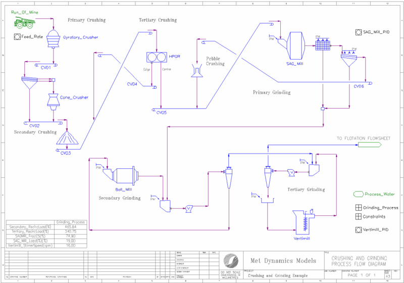
The project shows a multi-stage crushing and grinding circuit which consists of:
- Primary crushing
- Secondary crushing and screening
- Tertiary crushing using High Pressure Grinding Rolls (HPGR) with edge recycle
- Primary grinding with a Semi-Autogenous (SAG) mill, trommel and screen in closed circuit with a pebble crusher
- Secondary grinding with a ball mill and hydrocyclones in closed circuit
- Tertiary grinding with a stirred mill and hydrocyclones in closed circuit
A PID controller is used to limit the SAG mill speed to either a fixed volumetric load or the point where the mill media first impact the shell liner rather than the charge toe. A second PID controller adjusts the stirred mill speed to maintain a power draw set point.
The solids are represented by species designated as HardOre and SoftOre to represent the impacts of ore blending on simulated plant performance. Different hardness properties are applied to each solid species at the comminution units (crushers, HPGR, SAG, ball and stirred mills).
The values of number of calculated process parameters are compared to their maximum values (constraints) during the simulation solve. A General Controller calculates the ratio of each measured value to its limiting value and determines the maximum value of all ratios.
A PID controller adjusts the Run Of Mine ore feed until the maximum constraint ratio reaches a target value of 1.0. This represents the state where plant throughput is first constrained by equipment limitations. The process parameter exhibiting the maximum ratio of 1.0 identifies the location of the active throughput constraint.
Project Configuration
- The Met Dynamics - Crusher models in the primary, secondary and pebble crushing areas all use the Whiten method.
- The Met Dynamics - HPGR model in the tertiary crushing area uses the Torres HPGR method.
- The Met Dynamics - Mill model in the primary grinding area uses the AG/SAG (Variable Rates) method. The Media Trajectory calculation option is used to determine the point of media impact.
- The Met Dynamics - Screen models use the Vibrating (Metso) method (secondary screen, SAG screen) or the Vibrating (Whiten) method (SAG trommel).
- The Met Dynamics - Mill model in the secondary grinding area uses the Ball (Perfect Mixing) method. The Overfilling Indicator calculation option is used to identify if the mill is being overfilled at the simulated feed rate.
- The Met Dynamics - Mill model in the tertiary grinding area uses the Stirred (Perfect Mixing) method. The Nitta vertimill power calculation option is used to estimate the mill power draw.
- The Met Dynamics - Hydrocyclone models in the secondary and tertiary grinding areas both use the Narasimha-Mainza (2014) method.
- The Met Dynamics - Pump models in the secondary and tertiary grinding areas both use the Speed calculation mode.
Crushing, Grinding and Flotation Example
Project Location
..\SysCADXXX\Examples\09 MetDynamics\Crushing, Grinding and Flotation Example.spf
Available from Build 139.35544.
Features Demonstrated
- The use of Met Dynamics - Crusher
- The use of Met Dynamics - HPGR
- The use of Met Dynamics - Mill
- The use of Met Dynamics - Screen
- The use of Met Dynamics - Hydrocyclone
- The use of Met Dynamics - Flotation
- The use of Met Dynamics - Pump
Brief Project Description
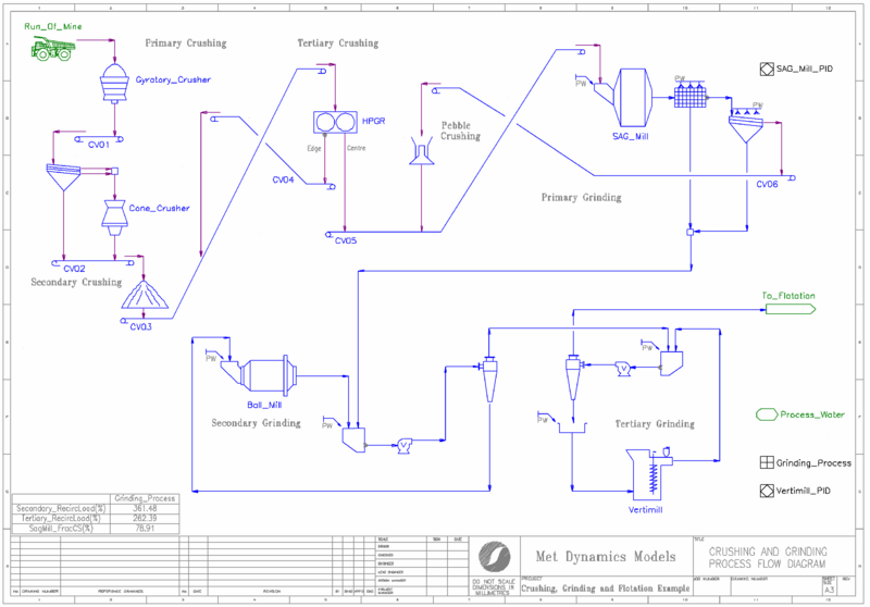
The project shows a multi-stage crushing and grinding circuit which consists of:
- Primary crushing
- Secondary crushing and screening
- Tertiary crushing using High Pressure Grinding Rolls (HPGR) with edge recycle
- Primary grinding with a Semi-Autogenous (SAG) mill, trommel and screen in closed circuit with a pebble crusher
- Secondary grinding with a ball mill and hydrocyclones in closed circuit
- Tertiary grinding with a stirred mill and hydrocyclones in open circuit
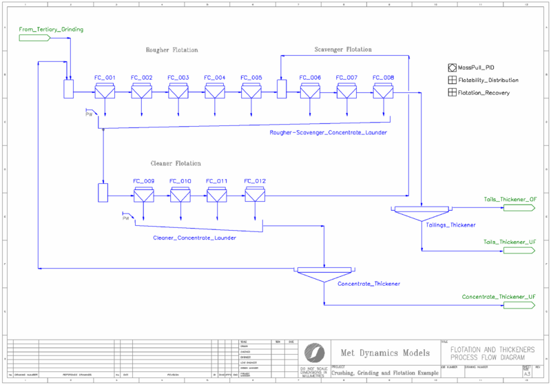
This is followed by a multi-stage flotation circuit which consists of:
- Rougher flotation with five mechanical flotation cells
- Scavenger flotation with three mechanical flotation cells
- Cleaner flotation with four mechanical flotation cells
- Concentrate and tailings thickeners
The important mineral solids are represented by distinct chemical species (Au, CuFeS2, FeS2 and CaCO3) with the rest assigned to a Non-Sulphide Gangue pseudo species (NSG).
A PID controller is used to limit the SAG mill speed to either the installed motor power or the point where the mill media first impact the shell liner rather than the charge toe. A second PID controller adjusts the stirred mill speed to maintain a power draw set point.
Mineral solids in the grinding circuit product are distributed amongst size fractions using the Bazin polynominal method (Bazin et al, 1994). The minerals solids are then distributed to flotability components-by-size (Fast/Slow/Non-Floating) prior to being fed to the flotation circuit. These actions are performed by a General Controller.
A final PID controller adjusts the air flow rate in the final rougher cell to achieve a circuit mass pull set point.
Project Configuration
- The Met Dynamics - Crusher models in the primary, secondary and pebble crushing areas all use the Whiten method.
- The Met Dynamics - HPGR model in the tertiary crushing area uses the Torres HPGR method.
- The Met Dynamics - Mill model in the primary grinding area uses the AG/SAG (Variable Rates) method. The Media Trajectory calculation option is used to determine the point of media impact.
- The Met Dynamics - Screen models use the Vibrating (Metso) method (secondary screen, SAG screen) or the Vibrating (Whiten) method (SAG trommel).
- The Met Dynamics - Mill model in the secondary grinding area uses the Ball (Perfect Mixing) method. The Overfilling Indicator calculation option is used to identify if the mill is being overfilled at the simulated feed rate.
- The Met Dynamics - Mill model in the tertiary grinding area uses the Stirred (Perfect Mixing) method. The Heath HIG mill power calculation option is used to estimate the mill power draw.
- The Met Dynamics - Hydrocyclone models in the secondary and tertiary grinding areas both use the Narasimha-Mainza (2014) method.
- The Met Dynamics - Pump models in the secondary and tertiary grinding areas both use the Speed calculation mode.
- All Met Dynamics - Flotation models use the Savassi method.
References
- Bazin, C., Grant, R., Cooper, M. and Tessier, R., 1994. A method to predict metallurgical performances as a function of fineness of grind. Minerals Engineering, 7(10), pp.1243-1251.
Gravity, Dense Medium and Magnetic Separation Example
Project Location ..\SysCADXXX\Examples\09 MetDynamics\Gravity, Dense Medium and Magnetic Separation Example
Available from Build 139.37014.
Features Demonstrated
- The use of Met Dynamics - Mill
- The use of Met Dynamics - Screen
- The use of Met Dynamics - Dense Medium Separator
- The use of Met Dynamics - Gravity Concentrator
- The use of Met Dynamics - Hydrocyclone
- The use of Met Dynamics - Classifier
- The use of Met Dynamics - Magnetic Separator
Brief Project Description
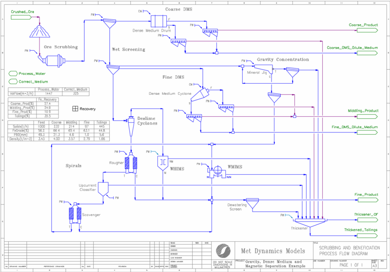
The project shows a beneficiation circuit which consists of:
- Ore scrubbing for size reduction
- Wet screening of ore into size fractions for downstream processing
- Dense Medium Separation (DMS) using a drum with sinks and floats screens, yielding a coarse upgraded product
- Gravity concentration using a mineral jig, yielding a middling upgraded product
- DMS using a cyclone with sinks and floats screens, yielding a middling product
- Deslime hydrocyclones feeding:
- Rougher-scavenger spiral concentrators with intermediate upcurrent classification
- Wet High Intensity Magnetic Separation (WHIMS) and Wet Medium Intensity Magnetic Separation (WMIMS)
- Dewatering screens and thickening, yielding a fine upgraded product and tails
The primary mineral solids are represented by the chemical species Fe3O4 and SiO2. The species are further subdivided into Individual Phases which represent both composition (% Fe) and density classes.
The ore scrubbing step redistributes particles sizes within each density class, allowing the beneficiation simulation to respond to size reduction changes (scrubber feed rate, feed size, power draw etc.).
Each of the dense medium, gravity concentration and hydraulic classification steps partition the mineral solids based on density and particle size. The magnetic separation steps recover mineral solids based on magnetic properties assigned by composition class.
Correct Medium is added to DMS units from a Makeup source. The Correct Medium consists of water (H2O) and ferrosilicon (FeSi) mixed to a specified density. For simplicity, the FeSi species has no associated particle size distribution and is assigned to the liquids (l) phase, so it follows water.
A General Controller calculates the mass yield, Fe recovery and Fe grade of the coarse, middling, and fine products, along with the tails.
Project Configuration
- The Met Dynamics - Mill model in the ore scrubbing area uses the multicomponent (ore-specific) Herbst-Fuerstenau method with a Natural Selection breakage function.
- The Met Dynamics - Screen models use the Vibrating (Metso) method (wet screens), the Vibrating (Whiten) method (sinks and floats screens), and the Dewatering (Ng) method for the dewatering screen.
- The Met Dynamics - Dense Medium Separator models use the Drum (Baguley) method (coarse drum) and the Partition (Pivot) method (middling cyclone).
- The Met Dynamics - Gravity Concentrator models use the Jig (King) method (middling jig) and the Partition (Pivot) method with reverse partitioning (rougher-scavenger spirals).
- The Met Dynamics - Hydrocyclone model uses the Narasimha-Mainza (2014) method for the deslime cyclone.
- The Met Dynamics - Classifier model uses the Gravity (Plitt-Flintoff) method for the upcurrent classifier.
- The Met Dynamics - Magnetic Separator models use the WHIMS (Dobby & Finch) method (WHIMS) and the WLIMS (King & Schneider) method (WMIMS).


