Met Dynamic - Dynamic Example Projects
Navigation: User Guide ➔ Example Projects ➔ 09 MetDynamics
Related Links: Met Dynamics - Steady State Examples
Dynamic Grinding Example
Project Location
..\SysCADXXX\\ExamplesDynamic\MetDynamics - Grinding Example.spf
Available from Build 139.36389.
Features Demonstrated
- The use of Met Dynamics - Mill
- The use of Met Dynamics - Hydrocyclone
- The use of Met Dynamics - Pump
Brief Project Description
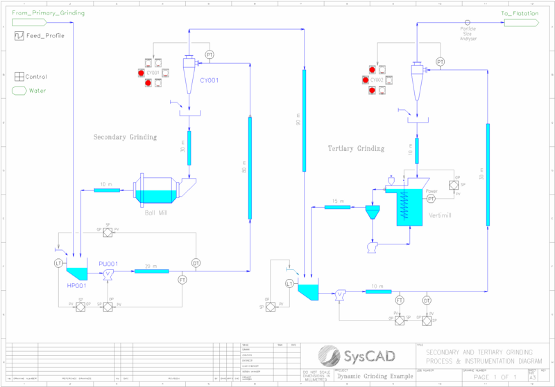
The project shows the dynamic simulation of a two-stage grinding circuit which consists of:
- Secondary grinding with a ball mill and hydrocyclones in closed circuit
- Tertiary grinding with a stirred mill and hydrocyclones in closed circuit
Solids in the circuit feed are represented by species designated as HardOre and SoftOre to demonstrate the impacts of ore blending on simulated plant performance. Different hardness properties are applied to each solid species at the ball and stirred mills.
A Profile unit model is used to change the hard-soft ore blend and the overall solids and liquids feed rates as simulated time progresses. This introduces disturbances into the circuit which the unit operations and control system must manage.
The ball and stirred mill models are configured in dynamic mode, which maintains solids and liquids inventories in the mill load. Grinding performance and residence time delays are automatically computed as the composition of the mill load changes.
Hydrocyclone models are actuated into on-off states and the resulting pressure drop across a cluster is continuously calculated for the changing feed rate and composition.
Centrifugal slurry pump models are used to determine the volumetric flow rate discharging from sumps based on pump impeller rotational speeds and slurry properties.
Tanks configured in Layered mode are used to simulate transport delays arising from piping systems of variable diameter and length. These delays can impact process control responses.
Transmitter unit models are used to simulate process instrumentation such as level, flow and density meters. First order filters are applied to limit signal noise and smooth controller responses, similarly to operating plants.
A system of PID controllers is used to manage sump levels, flow rates, cyclone feed pulp densities and mill power by adjusting pump speeds, mill speeds, and water addition rates. Cascade PID control is applied in some cases.
A General Controller unit model performs a number of process control logic and instrumentation tasks:
- The sumps are interlocked and pulp discharge shut off if operating levels become critically low.
- Hydrocyclones are actuated on or off to maintain cluster operating pressure set points. Frequent on-off cycling is prevented by a minimum cycle time counter.
- A Particle Size Analyser process instrument is simulated by sampling the tertiary cyclone overflow P80 at fixed periods.
Trend windows indicate sump levels, cyclone operation, and recirculating load.
The example project is intentionally configured to demonstrate stable secondary grinding and unstable tertiary grinding after an initial mill filling period.
Project Configuration
- The Met Dynamics - Mill model in the secondary grinding area uses the Ball (Perfect Mixing) method. The model is configured in Dynamic mode with an overflow-type discharge arrangement.
- The Met Dynamics - Mill model in the tertiary grinding area uses the Stirred (Perfect Mixing) method. The model is configured in Dynamic mode. The Nitta vertimill power calculation option is used to estimate the mill power draw.
- The Met Dynamics - Hydrocyclone models in the secondary and tertiary grinding areas both use the Narasimha-Mainza (2014) method.
- The Met Dynamics - Pump models in the secondary and tertiary grinding areas both use the Flow Rate calculation mode, as pump speed is adjusted by the PID controllers.
