Explorer Window: Difference between revisions
Merry.Huang (talk | contribs) mNo edit summary |
No edit summary |
||
| Line 1: | Line 1: | ||
'''Navigation: [[User Guide]] -> [[Windows]] -> Explorer Window | '''Navigation: [[User Guide]] -> [[Windows]] -> Explorer Window | ||
This page is for SysCAD 9.3 Build 137 or later. For earlier builds, including SysCAD 9.3 Build 136 and SysCAD 9.2, please see [[Explorer Window 9.3]]. | |||
== Introduction == | == Introduction == | ||
Revision as of 07:23, 24 October 2017
Navigation: User Guide -> Windows -> Explorer Window
This page is for SysCAD 9.3 Build 137 or later. For earlier builds, including SysCAD 9.3 Build 136 and SysCAD 9.2, please see Explorer Window 9.3.
Introduction
The SysCAD Explorer Window may be accessed in any of the following ways:
| Command Button | |||
| Command Path | View - Explorer | OR | Window - Select Window |
| Short Cut Key | Ctrl+E | OR | Ctrl+W |
This window contains information regarding the Graphics and Trend windows available in the project, as well as the units on each graphic.
The Explorer window is not constrained within the boundaries of the SysCAD window and may be moved beyond the SysCAD limits, and if the user has dual monitors (highly recommended) this window may be located on the alternate monitor.
This is a very useful feature, as the Explorer window in always on top and by moving it away from the SysCAD window you free up more space to view the actual project.
The image below shows a project with 6 graphics windows and 1 trend window:

|
Notes:
|
The user may navigate to any Graphics or Trend window in the project by simply clicking on the required window in the Explorer window. SysCAD will activate the required window. This is a really useful feature for a large project that contains many Graphics and / or Trend windows.
The windows are listed alphabetically in the Explorer window, as shown above. This is why it is often a good idea to number the flowsheets so that they follow the process flow, for example:
- 01 Crushing and Screening
- 02 Milling and Cycloning
- 03 Leaching
- 04 Counter Current Washing Circuit, etc.
The Graphics windows are all listed first, followed by the Trend windows.
Manipulating Graphics Windows (Flowsheets)
Overall Graphics Commands
By right clicking on 'Graphics' in the Explorer window the user will see the following pop up menu:

|
This allows the user to carry out a number of actions:
|
Individual Flowsheets
By right clicking on a Flowsheet name in the Explorer window the user will see the following pop up menu:
This allows the user to carry out a number of actions on the flowsheet:

|
|
The user may navigate to any unit model or pipe in the project by expanding the tree view and then clicking on the required unit or pipe in the Explorer window.
This is shown in the image below (this is for a small project with only a single Graphics page - so that it is easier to view the units)

Creating Equipment or Pipe List
The user may limit the units that are displayed by using the Filter at the bottom of the Explorer Window.
For example, if the user wishes to copy the pipes on a single graphics page, and the pipes all have the naming convention P_nnn, then in the filter window type P_.
The following view is shown:

The user may then copy all of the pipe tags on Graphics Window 05_Flowsheet to another application, such as Excel to form the basis of a report, see Excel Reports .
Models Marked with Red Cross
The model listing behaviour has changed in SysCAD 9.2 Build 135.14291. In this build (or later), only missing models will be marked with red cross.
A Missing Model refers to a SysCAD unit model that's been deleted, but the Graphics still exist.
This could be a result from the following actions:
- A SysCAD unit model/graphics page has been deleted
- User closes graphics page without saving
- User then saves the project. (Closed graphics page will NOT be saved)
- User then closes and opens the project, and reopens the graphics page (that was not saved).
As a result, the model has been deleted from the database but the graphics file has not been updated, thus causing the mismatch.
The easiest way to check for missing models is by looking at the Graphics page directly (not from Explorer). If miss model exists, the models would appear grey and there is no access window when you click on them.
The recommended action for Missing Model with graphics is to delete all the dummy graphics using Graphics - Delete, then re-build the flowsheet.
For SysCAD builds SysCAD 9.2 Build 135.14290 or earlier, two other types of Tags may appear with "red crosses" next to them. These inlcude:
- Tear Flange (usually contain “ <>” or “Flng” in the Tag) - Please NOTE that these only appear in the explorer if the Tear (group) is hidden.
- Direct Links / Makeup streams
These Red Crosses means SysCAD can’t create a hot jump to Tear / Direct Link directly from the Explorer window, it does NOT mean the model is missing. So while checking for missing models please ignore these tags.

This problem has been rectified in SysCAD 9.2 Build 135.14291.
Missing Graphics
It is possible to get into a situation where "orphan" models without Graphics Representation exist in the SysCAD project.
The missing Graphics could be due to user accidentally closing the Graphics Page, or Graphics Symbol got "corrupted" and has gone missing, thus creating "orphan" models without graphics representation.
- If the models are valid and must exist, then the graphic symbols should be added back to the project.
- In the case of missing an entire page: try and located the missing graphic page from previously saved versions, copy back into the project and open it using Open file: "xxxx.scg"
- In the case of missing single Graphics Symbol:
- In the empty spaces where the graphics should be, use Graphics-Insert Symbol to add back an appropriate Graphics Symbol. (This is a dummy symbol)
- Use Graphics - Construct Symbol to attached this dummy symbol to an orphan model. (See also Manipulating_Graphics)
- If the Orphan models in the project are NOT required, then user can delete these orphan models using the Explorer Window:
- From the section called Missing Graphics under the graphics tree, open that tree to get a list of all the unit operations in the project without graphics.
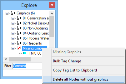
- If user wish to delete all the orphan models, simply right click on the word Missing Graphics to bring up a popup menu, select the option to Delete all nodes without graphics.
- From the section called Missing Graphics under the graphics tree, open that tree to get a list of all the unit operations in the project without graphics.
- Once that is done, save the project, close and reopen Explorer to refresh the explorer list. User should find that the missing graphics is fixed.
