Example - 06 OLI Projects
Navigation: User Guide ➔ Example Projects ➔ 06 OLI
Related Links: OLI Overview
Simple Reactor Example
Project Location
..\SysCADXXX\Examples\06 OLI\OLIFull\SimpleReactor.spf
Available from Build 139.31866.
Features Demonstrated
- The use of OLI Model Configuration
- The use of OLI Reactor 2
- The use of OLI SideCalc
Brief Project Description
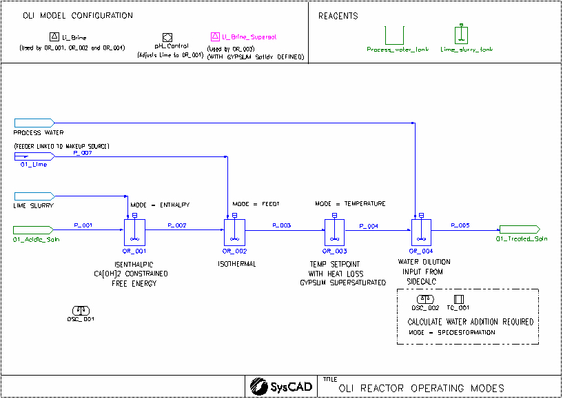
In this demo project, we demonstrate several different operating modes for the OLI reactor.
- Isenthalpic, temperature of the output is calculated for an acid-base reaction
- Isothermal, temperature is set to the temperature of the incoming stream mixture, heat flow required to achieve this is calculated
- A temperature setpoint is set, heat loss is also incorporated
- This tank is linked with a side calculation. The side calculation is doing a calculation to determine the water required to dissolve the gypsum coming into the tank. The calculated water flow is then applied to the makeup of the actual reactor tank. This demonstrates a feed-forward control strategy for water addition
- Each OLI project must contain at least one OLI Model Configuration model.
- We have used two OLI Model Configuration models in this project, one we allow supersaturation of gypsum.
Project Configuration
- The Li_Brine database is used by the OR_001, OR_002 and OR_004 units.
- A second Li_Brine database (Li_Brine_Supersat) is used by the PR_003 unit to emulate the Gypsum being supersaturated.
- CaSO4:2H2O(s)(Gypsum) formation has been suppressed in the "OLIConfig" tab.
- Salts First algorithm has been selected for species re-building in both model configuration files. See Reverse Mapping section for more details.
- OR_001
- Ca(OH)2 addition is being constrained, this is done by ticking "UseCFE" and in the CFE tab: Ca(OH)2 has 5% inert fraction.
- Calculation mode is isenthalpic (delta enthalpy = 0 kW)
- We found gypsum precipitation occurs and a slight pickup in tank temperature due to reaction. There are some Ca(OH)2 remaining due to the user specified inert fraction
- OR_002
- Calculation mode is isothermal (Final T = Feed T), heat flow required to achieve this is shown in the OLIResults, Energy balance section.
- Ca(OH)2 addition is fully used and gypsum precipitation occurred
- OR_003
- Calculation mode is user specified temperature, heat flow required to achieve this is shown in the OLIResults, Energy balance section.
- This reactor also suppresses the formation of gypsum, allowing gypsum to be supersaturated.
- Heat loss is also being used in this model.
- OR_004 and OSC_001
- The OSC_001 has been set up to determine the water required to dissolve the gypsum coming into OR_004. The calculated water flow is then applied to the makeup of the actual reactor tank. This demonstrates a feed-forward control strategy for water addition.
Acid Recovery - Nanofiltration Example
Project Location
..\SysCADXXX\Examples\06 OLI\OLIFull\AcidRecovery_NF.spf
Available from Build 139.31866.
Features Demonstrated
- The use of OLI Model Configuration
- The use of OLI Reverse Osmosis Unit
Brief Project Description
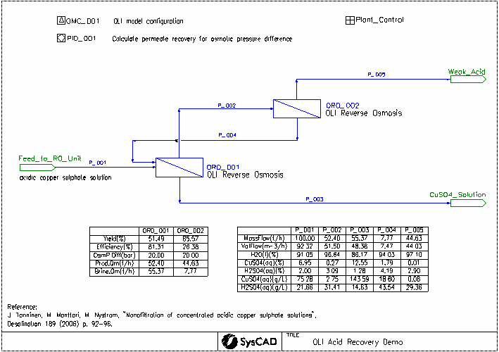
This project was created based on the paper: "Nanofiltration of concentrated acidic copper sulphate solutions". See reference below. It looks at the separation of sulfuric acid from copper sulfate at high salt and acid concentrations. OLI Reverse Osmosis Unit is used to simulate the nanofiltration units.
Reference:
- J. Tanninen, M. Manttari, M. Nystrom, "Nanofiltration of concentrated acidic copper sulphate solutions", Desalination 189 (2006) p. 92-96.
Project Configuration
- The CuSO4_H2SO4.dbs database is used. This was generated using the OLI MSE framework.
- Salts First algorithm has been selected for species re-building. See Reverse Mapping section for more details.
- OR0_001
- Efficiency Method set to Ionic Permeability.
- Yield required controlled by OsmP difference value, set to 20 bar in the PID controller.
- A concentration polarization factor of 120% is applied.
- Ion permeability is set by the Plant_Control General Controller
- OR0_002
- Efficiency Method set to Ionic Permeability.
- Yield required controlled by OsmP difference value, set to 20 bar in the PID controller.
- A concentration polarization factor of 120% is applied.
- Ion permeability is set by the Plant_Control General Controller
For both of the OLI reverse osmosis units, the following streams are calculated using OLI:
- Input: The combined input streams at equilibrium
- Output: The brine solution leaving the unit at equilibrium
- MembraneInterface: The brine solution at the membrane interface, which is more concentrated than the Output stream due to concentration polarization
- Product: The acid solution which has passed through the membrane
The osmotic pressure difference is calculated between the MembraneInterface and the Product.
Potash Crystallisation Example Project
Project Location
This is a Steady State project and is stored at:
..\SysCADXXX\Examples\06 OLI\OLIFull\Potash_Crystallisation.spf
Available from Build 139.31866.
Features Demonstrated
- The Use of OLI Model Configuration - with an OLI potash database file (potash.dbs).
- Setting up flash trains using OLI Evaporator with Shell and Tube Heat Exchanger 2 & Barometric Condenser.
NOTE: This is similar to the Potash example project, but instead of using the Potash add-on, it is using the OLI Solver.
Brief Project Description
- This is a MOP (Muriate of Potash) example project.
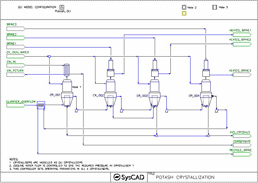
- This project shows a 4-Stage-Evaporator(crystalliser) circuit.
- This project uses constant feed for Liquor Feed and Brine streams.
- Crystallisation is based on OLI solver solution.
- Dilution water is added to each crystallisation stage.
- PotashEvaporator underflow (crystallised material) is removed from the first third and fourth stage. Second stage underflow is feed to the 3rd stage.
- Brine is used to exchange heat in the Barometric condensers.
Project Configuration
- The potash.dbs database is used. This is generated using the OLI MSE framework.
OLI Evaporator
- OLIEvaporator Tab
- Select FlashTrain mode
- Specify minimum flash temperature for the unit (this will assist with pressure balance of the circuit)
- Set up the TCE tab page - use "Potash_OLI"
- Set up the Separ tab page - required Overflow and Underflow solids.
- Set up dilution water to the crystalliser.
Barometric Condenser
- Set the approach temperature.
Shell and Tube Heat Exchange
- HX_001 is used to condense the flash steam from the 1st Crystalliser,
- Method - CondensingSteam
- Condensing Method: Demand (UA)
- Demand Connection: FlashTrain
- The condenser area and HTC information is supplied.
- HX_002 is used to preheat the feed with recycle Brine
- Method - Sensible HX
- The heater area and HTC information is supplied.
Demo OLI Lithium Carbonate Acid Leach Project
NOTE: The following example is for OLI released with 9.3 Build 137. In Build 139.31866, a new set of OLI models have been released, and the Build 137 models have been archived as Legacy. The legacy models and the following project will be discontinued in the next major release (Build 140), please change and existing projects to use the new set of models as soon as possible.
Project Location
..\SysCADXXX\Examples\06 OLI\OLILegacy\Demo OLI Lithium Carbonate Acid Leach Project.spf
Features Demonstrated
- The use of OLI Chemistry Model
- The use of OLI Reactor to perform side calculations
- The use of Thickener model
- The use of Filter Press model
- The use of Composition Fetch in Feeder model
- The use of Makeup Sources and Makeup Blocks
- The use of Reaction Blocks, including the use of Heat Exchange, Override Product Temperature Option and Final Flow extent type
- The use of Set Tag Controllers
- The use of a PID Controller
- The use of EHX
- The use of Split Flows Gas Vent option
Brief Project Description
- This is a simplified model of a Lithium Carbonate plant. The project is based on the Quebec Lithium Project in Canada, as described in "Technical Report NI 43-101 on the Pre-Feasibility Study for the Quebec Lithium Project", by Canada Lithium Corporation and BBA Inc, May 2010, which was downloaded from the Sedar website (http://www.sedar.com/DisplayCompanyDocuments.do?lang=EN&issuerNo=00007891).
- It is very similar to the Demo Lithium Carbonate Acid Leach Project except in a couple of places it uses OLI to predict reaction extents and pH.
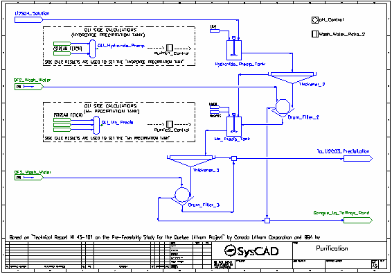
- Four parts of the process are mimicked in OLI Reactors using the Composition Fetch functionality in the feeders and Set Tag Controller to transfer results to corresponding reaction blocks. The four processes are:
- Water Leach
- Hydroxide Precipitation
- Manganese Precipitation
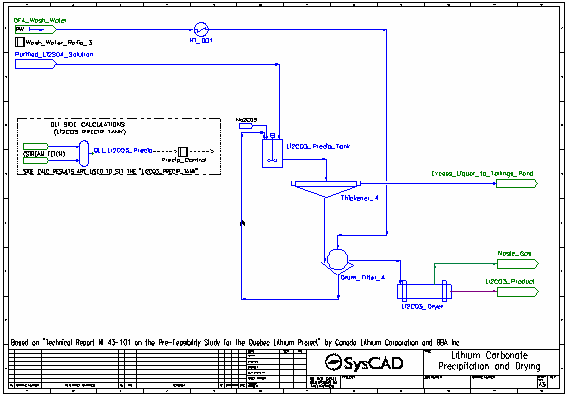
- Lithium Carbonate Precipitation
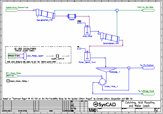
- Dried spodumene concentrate is fed into the Decrepitation Kiln, where alpha-spodumene is converted to beta-spodumene and any water present is evaporated. These reactions occur at 1050 °C.
- The solid product is cooled to 60 °C in the Cooler.
- Cooled solid product is mixed with concentrated sulfuric acid in the Acid Mixer.
- The slurry from the Acid Mixer is fed to the Sulphatation Kiln where the beta-spodumene is converted to solid lithium sulfate by reacting with the sulfuric acid. Oxide impurities are also converted to their sulfate forms by reaction with sulfuric acid. These reactions occur at 250 °C.
- Some excess water is converted to gas. All gases are vented.
- The kiln solids, along with leftover acid, pass to the Water Leach Tank where water is added.
- The majority of the reactions in the Water Leach Tank are set by the Leach Control controller which measures the results generated by OLI in the OLI Water Leach OLI Reactor.
- The slurry is thickened and send to a drum filter where it is washed with process water. The washed filter cake is sent to the Tailings Pond.
- The filtrate and thickener overflow are combined and sent to the purification processes.
- The pH of the lithium sulfate solution is raised from around 3 to around 6 by the addition of Lime. The pH is calculated by the corresponding OLI Reactor, OLI Hydroxide Precip, and the addition of the Lime is controlled by a PID Controller.
- The Lime neutralises most of the acid present as well as participating in precipitation reactions.
- The majority of the reactions in the Hydroxide Precip Tank are set by the Purific1 Control controller which measures the results generated by OLI in the OLI Hydroxide Precip OLI Reactor.
- The resulting slurry is thickened and send to a drum filter where it is washed with process water. The washed filter cake is sent to the Tailings Pond.
- The filtrate and thickener overflow are combined and sent to the second stage of purification.
- The pH of the solution is raised to 10 by the addition of Caustic Soda (NaOH). The pH is calculated by the corresponding OLI Reactor, OLI Mn Precip, and the addition of the NaOH is controlled by a PID Controller.
- The NaOH both neutralises all remaining acid present as well as participating in precipitation reactions. Soda Ash is also added to aid in the precipitation of carbonates.
- The majority of the reactions in the Mn Precip Tank are set by the Purific2 Control controller which measures the results generated by OLI in the OLI Mn Precip OLI Reactor.
- The resulting slurry is thickened and send to a drum filter where it is washed with process water. The washed filter cake is sent to the Tailings Pond.
- The filtrate and thickener overflow are combined and sent to the lithium carbonate precipitation tank which is maintained at 95 °C.
- Soda Ash is added to convert the lithium sulfate to lithium carbonate (which precipitates), as well as precipitate other carbonates.
- The majority of the reactions in the Li2CO3 Precip Tank are set by the Precip Control controller which measures the results generated by OLI in the OLI Li2CO3 Precip OLI Reactor.
- The resulting slurry is thickened and send to a drum filter. The thickener overflow is sent to the Tailings Pond.
- The thickened slurry is washed with process water (also at 95 °C) in the drum filter. The washed filter cake is sent to the dryer, while the filtrate is recycled back to the lithium carbonate precipitation tank.
- In the dryer, all water is evaporated and aqueous species are returned to the their solid forms. The steam is vented leaving the solid lithium carbonate product.
Project Configuration
- Most units with reactions are simulated by the Tank model. This includes the Decrepitation Kiln, Sulphatation Kiln, Water Leach Tank, Hydroxide Precip Tank, Mn Precip Tank, Li2CO3 Precip Tank and Li2CO3 Dryer.
- Four OLI Reactors are used to perform side calculations (using the Side Calc model). The results used include pH and final solid flows to set dissolution and precipitation reactions.
- The reactions set based on OLI predictions use the Final Flow extent type.
- Separation of gases and slurry is usually achieved by the use of Split Flows Gas Vent option.
- Makeup Blocks are used:
- in the Acid Mixer to add a slight excess sulfuric acid
- in the Water Leach Tank to add process water to achieve a specified solids fraction
- in the Hydroxide Precip Tank to add a controlled mass flow of lime solution
- in the Mn Precip Tank to add a controlled mass flow of NaOH solution
- in the Mn Precip Tank to add a stoichiometric amount of Na2CO3
- in the Li2CO3 Precip Tank to add a stoichiometric amount of Na2CO3
- The Cooler is modelled by a Tank with the EHX sub-model enabled to achieve the desired product temperature
- All Thickeners are modelled by the Thickener model using the OverFlowSolidsFraction method.
- All Drum Filters are modelled by the Filter Press model using the SolidsFractionInFiltrate and Constant Wash Efficiency methods.
- Set Tag Controllers are used to set wash water flows based on user specified ratios to all drum filters and to set final flows of species in reaction blocks (based on OLI predictions).
- PID Controllers are used to control the Lime and Caustic Soda additions in order to achieve the desired pH, based on OLI calculations of pH.
Included Excel Report
Lithium Acid Leach Example Report.xlsx
This file has the following reports:
- Criteria
- Streams
- Mass Balance
