TCE Species Mapping
Navigation: Models ➔ TCE Models ➔ Thermodynamic Calculation Engines ➔ TCE Species Mapping
| Thermodynamic Calculation Engines (TCEs) | TCE Options | TCE FAQ | |||||
|---|---|---|---|---|---|---|---|
| TCE Functionality Overview | TCE Species Mapping | TCE Configuration Options | AQSol | ChemApp | PHREEQC | OLI | |
Latest SysCAD Version: 13 May 2026 - SysCAD Build 139.37082
Mapping Overview
Mapping between SysCAD streams and TCE streams is done as shown in the diagram below. The focus here is on mapping of mass (conserving elemental mass balance). The dotted areas represent the control volumes applicable to each type of thermodynamic calculation. The Unit Operation, or the black control volume, incorporates forward mapping, calculation, and reverse mapping. Unit operations would include reactors, evaporators, reverse osmosis units, and solvent extraction units. The Side Calculation, or the red control volume, is used to read one or more streams and perform a specific calculation. It can be used as a virtual sensor in the model, and is often used to determine reaction extents for SysCAD reaction blocks. The Direct Calculation, or green control volume, does not use mapping at all. As mentioned previously, it is a direct interface to the thermodynamic software. The Direct Calculation is a user interface for performing single point calculations and generating trends, similar to how one would typically use thermodynamic software directly.

Mapping
Each of the thermodynamic calculation engines that link to SysCAD require mapping to convert a SysCAD stream into a representation suitable for the thermodynamic engine. In general, mapping between SysCAD species and ions, and species contained within the thermodynamic model, consists of two steps:
- Forward Mapping is used to convert SysCAD species to species within the thermodynamic model
- All unit operations that take data from SysCAD streams require a forward mapping step. This includes all TCE unit types except Direct Calculation and Feeder.
- Reverse Mapping is used to convert calculated speciation from the thermodynamic model solution back into SysCAD species.
- When all species predicted by a TCE equilibrium solution are directly mapped to SysCAD species, reverse mapping is quite straightforward. In this case, each species is simply passed into the mapped SysCAD stream species.
- However, when there are ion mappings involved, the situation is much more complex. In this case, the ion breakdown reactions for each SysCAD species are used to reassemble the SysCAD species.
- These are done using specialized algorithms to determine the most likely apparent species from ionic species. Details on this algorithm are provided in Reverse Mapping Algorithms.
Forward Mapping
The mapping types are:
- Direct mapping: there is a TCE species with matching phase, elemental composition, and charge to that of a SysCAD species
- Ion mapping: there is a TCE species with matching phase, elemental composition, and charge to a SysCAD Ion (defined in the IonList.txt file)
- Note that in the case where a species can be directly or ion mapped, direct mapping always takes precedence.
The following applies in Forward Mapping:
- All non aqueous species will be mapped using direct mapping. The exception to this rule is AQSol, where all non-aqueous species are broken down.
- Aqueous species will be mapped using (in order of priority):
- direct mapping, if possible
- ion mapping, if possible, using ions in the IonList file
- All aqueous species which do not have a direct mapping, but have a corresponding ion breakdown pathway, will be broken down into ions using the IonList file
- Any species which do not have direct mapping or ion mapping to the thermodynamic engine will be bypassed and a warning will be issued to the user.
- The Ionlist file is stored within the project cfgfiles folder, see Ion Definitions.
- Please note that ChemApp typically only uses direct mapping, unless an aqueous database is used and the user selects the option to use ions using the Ionlist file.
A typical set of breakdown reactions is given below:
H2O(l) = OH- + H+
H2SO4(aq) = SO4-- + 2H+
H2SO4(l) = SO4-- + 2H+
HCl(aq) = H+ + Cl-
Na2SO4(aq) = SO4-- + 2Na+
NaCl(aq) = Na+ + Cl-
NaOH(aq) = OH- + Na+
HSO4- = SO4-- + H+
NaSO4- = SO4-- + Na+
Species that are mapped by ions undergo a reaction like this to form an ion that is recognized by the TCE.
- An example of forward mapping to an OLI reactor is shown below:

- In this case, the first access window shows the composition of the SysCAD feed stream. The second access window shows the OLI stream composition that is a result of forward mapping and will be used by OLI to calculate the equilibrium composition.
- In this case, there is a ion map between NaCl(aq) in the SysCAD stream and the Na+ and Cl- ions of the OLI model.
Reverse Mapping
The following applies in Reverse Mapping:
- Used when TCE species need to be converted back into SysCAD species, such as any of the TCE flowsheet unit operations (TCE Reactor, etc.).
- Direct mappings are where a TCE species directly correlates to an equivalent SysCAD species. These are usually solids, gases, and neutral liquid species.
- For reverse mapping requiring assembly of TCE ions into SysCAD species, the following steps are done:
- Ions predicted by TCE are first assembled into aqueous SysCAD species to the greatest extent possible by a user-selected algorithm Reverse Mapping Algorithms.
- Remaining ions predicted by TCE are then broken down using ionic breakdown reactions to primary ions, i.e. ions which cannot break into smaller ions.
- The primary ions are then assembled into aqueous SysCAD species in a manner similar to point 1.
- An example of reverse mapping from a PHREEQC evaporator to the product stream is shown below:
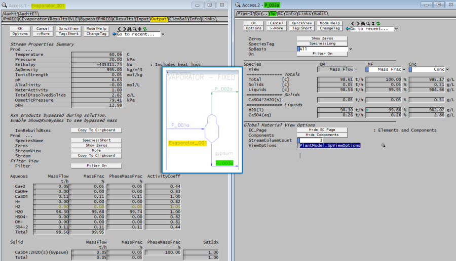

- In this case, the PHREEQC equilibrium composition predicts a number of different ions.
- The reverse mapping algorithm uses various ionic to species assembly reactions to calculate the SysCAD species, which in this case, is dissolved CaSO4(aq). In this case, the assembly reaction is SO4-- + Ca++ = CaSO4(aq).
- Any additional H+ and OH- species are combined to form water.
- Full elemental balance checks are provided to ensure that all elemental mass has been properly accounted for.
- Note that in the above example, H2 is predicted by PHREEQC but no equivalent SysCAD species (i.e. H2(aq)) is defined, and therefore, H2 is unmapped. However, its mass is very small.
Reverse Mapping Algorithms
The user-selected Reverse Mapping Algorithms are (selected from the TCE_ModelCfg model):
- Simple Extent of reaction
- Using initial vector of primary ions, determine which reversed breakdown reactions, i.e. formation reactions, have the greatest possible extent
- For greatest possible extent, we completely consume the limiting reagent
- Salts First (recommended method)
- Now we first process only species which are salts, i.e. do not contain H+ or OH-
- For this smaller group, do as per Simple extent of reaction
- Then do the same for acids/bases, i.e. those that contain H+, OH-
Option for reverse mapping algorithm:
- RevIonMap.BreakdownFirst: Available from Build 139.32979. When checked (original behaviour), the algorithm breaks all ions into their smallest parts before forming salts, acids, and bases. When not checked (recommended), the algorithm first attempts to form species from ions predicted by the equilibrium solution, followed by breaking down into their smallest parts.
NOTES:
- The recommendation is to use Salts First algorithm and NOT select RevIonMap.BreakdownFirst.
- Acids and bases will react violently to form a salt in almost all cases.
- Therefore, must prioritise salts to avoid possibility of forming bases and acids together.
- Please see example 2 below for a reverse mapping example containing brine.
- In both algorithms, the last reaction to be executed is always the formation of water from H+ and OH-.
- The reverse mapping functionality in SysCAD is a tool to help the user to predict salts and bases or acids which form, but it requires the user to add the appropriate species to the SysCAD species database.
- To assist the user, it provides warnings if acids and bases are present together in a solution, as this is not usually expected. In this case, the user must determine what additional species are required.
Example 1:
| Feed to Reactor | Product reverse mapping using Simple extent of reaction |
Product reverse mapping using Salts first |
|---|---|---|
Ca++ = 1 mole SO4-- = 2 moles Na+ = 1 mole H+ = 1 mole |
Results order is:
Ca++ + SO4-- = CaSO4 H+ + 0.5 SO4-- = 0.5 H2SO4 Na+ + 0.5 SO4-- = 0.5 Na2SO4 |
Resulting order is:
Ca++ + SO4-- = CaSO4 Na+ + 0.5 SO4-- = 0.5 Na2SO4 H+ + 0.5 SO4-- = 0.5 H2SO4 |
Example 2:
- Using an AQSol example, we have the following feed: 55% Water, 15% H2SO4 and 30% NaCl. The resulting SysCAD species are quite different depending on the reverse mapping algorithm selected, as shown in the following table. P_003 is the feed, P_004 is the product.
| Product reverse mapping using Simple extent of reaction |
Product reverse mapping using Salts first |
Comments |
|---|---|---|
 |

|
|
Unmapped/Bypassed Species
Unmapped/Bypassed Species in Forward Mapping
When a SysCAD stream contains a species for which there is no equivalent species in the TCE, it bypasses the TCE solver and is added to an Unmapped stream. The user gets a warning in this case. When a user specifically specifies a bypass, this is added to the Bypass stream. The user does not get a warning in this case, as it is based on a user specification. Both of these streams are added to the final TCE stream.
A third type of stream is the reaction bypass stream. This is used primarily when a TCE (that does not have its own VLE capabilities) is used in conjunction with the SysCAD VLE model. In this case, both a TCE solution and a vapour stream in equilibrium with the TCE solution is produced.

The solution here is to select or generate a different database for use with the TCE which includes the species you are trying to map. Alternately, the user may purposely bypass the species (or ensure they are not in the feed). Note that in the case where SysCAD VLE is used together with a TCE, species may be generated which are not represented within the TCE. These form a reaction bypass stream which is considered part of the TCE solution. This can be used where a TCE is defined for the aqueous phase only.
Unmapped Species in Reverse Mapping
When a TCE solver predicts the formation of a species for which there is no equivalent species in SysCAD, this results in the unmapped species being reported as an error. The model is switched to a side calculation.

The ideal solution here is to add species to the SysCAD database to enable mapping to a SysCAD stream. Alternate solutions include: suppress solids in ModelCfg so they do not form (e.g. trace amounts and/or slow kinetics); check inputs and settings to review if this is a valid case; bypass or use CFE on some species to change the conditions; or use the TCE calculation as a side calculation.
Unmapped Ions in Reverse Mapping
When a TCE solver predicts the formation of ions for which there is no species that can be formed from them in SysCAD, this results in the unmapped ions being reported as an error and the model switched to a side calculation.

The ideal solution here is to add liquid/aqueous phase species to the SysCAD database to enable formation of the SysCAD species from the ions (ions are aqueous). Alternate solutions include: check inputs and settings to review if this is a valid case; bypass or use CFE on some species to change the conditions; or use the TCE calculation as a side calculation.
For example, if the ions Na+ and Cl- are reported as unmapped ions, the solution is to add NaCl(aq) to the SysCAD database.
Common Error Messages
Some of the common errors users may encountered are:
After load of a new project or new TCE database
- Missing Ions: this occurs when there are ions in the TCE database which are not in the IonList.txt file. If this happens, you will be notified by error conditions on the TCEModelCfg (1st tab), as shown in the AQSol example below
 .
.
- To fix the error, go to the TCEConfig tab (2nd tab) and press

 . This action will add the missing ion for you automatically. You will get a notification in the Message Window.
- For example: AMC_001 1 Ions Added
- Then close and reopen the project, on the 2nd tab of TCEModelCfg model, press

 to make sure all the ions are mapped.
- To fix the error, go to the TCEConfig tab (2nd tab) and press
- Ions are mapped to SysCAD species and ions: this occurs when there are ions in the TCE database which can map to both ions in the IonList.txt file and ions defined as SysCAD species in the SysCAD database.
- If this happens, remove those ions from the SysCAD database so that they only occur in the IonList.txt file OR remove those ions from the IonList.txt file so that they only occur in the SysCAD database.
- Then close and reopen the project, on the 2nd tab of TCEModelCfg model, press to make sure all the ions are mapped.

After solve of the project
- Unmapped Species: this usually means the species maybe missing in the database (or not mapped in the TMC model). In the example shown below, CO2 is unmapped, to fix, add CO2(g) to the SysCAD.93.db3 and try again.
- Unmapped Ion: this usually means there are ions left over that cannot reform into an aqueous species. In the example shown below, we have 3 unmapped ions, H+, F- and Br-, this would indicate that HBr(aq) and HF(aq) are missing in the database, add these two species to the SysCAD.93.db3 and try again.

Enthalpy Reporting
Overview
The use of TCE calculations at discrete locations within an overall flowsheet introduces the use of different enthalpy models at different locations in the flowsheet. Within any TCE unit, the enthalpy values reported on the Input and Output tabs are generally calculated by the TCE. On the other hand, the enthalpy values reported by SysCAD streams entering and leaving the unit are calculated by SysCAD Species Property Models. We have two systems for enthalpy calculations. It is important to understand this interaction for correct interpretation of simulation results.
The best location for a quick check on comparative enthalpy values between TCE and SysCAD is in the Reverse Mapping Summary display on TCE results tab page. This shows, after a successful mass reverse mapping, the enthalpy reported by TCE and SysCAD displayed side by side together with the difference. Ideally these numbers should be close for consistency across the flowsheet between the two systems. Where there are significant differences (and the user accepts the TCE Output stream and species mapping as valid), then the user should investigate updating the project SysCAD species database enthalpy (Cp) data to achieve better compatibility between the systems.
For some cases, depending on TCE used, stream composition, input stream mixing and settings in unit model used, the displayed Input TCE enthalpy value may not necessarily reflect the expected or valid enthalpy value from the TCE. Take care using the reported TCE Input stream enthalpy value - some understanding of the TCE enthalpy calculations and the specific use case is required.
The PHREEQC TCE does not include an enthalpy model. For PHREEQC all enthalpy values are calculated by SysCAD. It is therefore recommended that the user takes care entering and reviewing SysCAD species database enthalpy (Cp) data for species of interest. The PHREEQC Input and Output enthalpy values reported are simply a copy of the SysCAD stream enthalpy before/after mapping. Completely successful mapping is required to use these reported enthalpy values.
Enthalpy Values Displayed
The figure below, for a simple case, shows the calculation of enthalpy during a TCE calculation. The four enthalpy values indicated are:
|

|
It is important to note in this example that the calculated enthalpy values are not equal but are quite close. This is the desired case and expected when there is "good" enthalpy (Cp) data for species in the Species Database for the project. If there are significant differences, the SysCAD species data for the project should be reviewed!
Calculate Enthalpy Balance
Available from Build 139.37022.
When using the TCE unit models, depending on the selected operating mode, users can choose to complete the enthalpy balance using TCE database values and compare them against the enthalpy values calculated using SysCAD database values. It is important to understand what selecting the CalcEnthalpyBalance option entails. This option means performing an Enthalpy Balance using TCE enthalpy values, which may significantly increase the number of TCE engine calls under certain conditions.
For a typical TCE unit model, such as the reactor, we will have the following operating modes:
Operating Mode (OpMode) Calculate Enthalpy Balance (CalcEnthalpyBalance checkbox) AQSol ChemApp OLI PHREEQC Temperature Optional Optional Optional SysCAD Enthalpy Balance only FeedT Optional Optional Optional SysCAD Enthalpy Balance only Enthalpy (SysCAD) Always On Not Available Always On Always On Enthalpy TCE Always On Always On Always On Not Available PhaseFormation Optional ChemApp Full only Optional SysCAD Enthalpy Balance only SpeciesFormation Optional ChemApp Full only Optional SysCAD Enthalpy Balance only
For example, if we have a reactor with two input streams, to evaluate the enthalpy balance, we need to determine the enthalpy in and out using TCE database values. Therefore, a TCE equilibrium calculation must be performed on each input stream to obtain the total enthalpy in. If the Operation Mode is set to Enthalpy, we may need to iterate on the output streams to achieve the correct temperature to maintain the input enthalpy values. Thus, for a reactor unit with two input streams using the Enthalpy method, a minimum of three TCE Equilibrium calculations are required to generate the energy balance data. For more complex TCE units, there could be many calls to the TCE engine during a single SysCAD iteration. To find out the statistics on how many calls to the TCE engines are made by each TCE unit, see the 'Used By' tab in the AQSol / ChemApp / OLI / PHREEQC Model Configuration model.
If CalcEnthalpyBalance is off, SysCAD will only calculate the enthalpy values for the product stream, significantly reducing the number of calls to the TCE engine. This approach can reduce computation time if the enthalpy balance around the unit using TCE enthalpy values is not critical. Note that even though the balance value (delta enthalpy) is not calculated, the enthalpy value for the output stream is still determined by performing the TCE equilibrium calculation.
Depending on the selection of the CalcEnthalpyBalance option, the Enthalpy Values Displayed under the TCE Results tab will either include or exclude the TCE Energy Balance section and the enthalpy values for the input streams.
Individual versus combined streams
In many cases, the way that streams are added will affect the calculated TCE feed enthalpy, and thus, the results. For streams which are expected to react when mixed in the reactor, users should have these as separate input streams to the unit, rather than combining them into a single stream. This is because for many situations, it is appropriate to calculate the TCE enthalpy of the incoming stream as if it were at equilibrium at the stream temperature. Consider the following example where sulphuric acid solution at 25 C and lime slurry, also at 25 C, are being added to a tank using OLI in constant OLI enthalpy mode (adiabatic in OLI enthalpy context). In both cases shown below, the equilibrium composition of the feed stream(s) at the specified temperature and pressure is used to calculate the feed stream enthalpy.
Below, a tie has been used upstream to mix the two streams containing acid and lime. No reactions are defined in the tie. This is incorrect and the temperature of the Treated Solution (OLI reactor output) is predicted to be 25.1 C:

The above example is incorrect because what OLI sees is the equilibrium composition at the feed temperature, which in this case, is a saturated gypsum stream. It is also notable that, as a sanity check, SysCAD will output its calculated enthalpy change, and in this case, the enthalpy change calculated by SysCAD would be very large (i.e. approximately equal to the heat of reaction as calculated by SysCAD).
In the second example below, the two streams are added directly to the OLI reactor. This is correct and the Treated Solution temperature (OLI reactor output) is predicted to be 43.6 C:

For the first case, the OLI reactor calculates the TCE equilibrium enthalpy of the single inlet stream. For the second case it separately calculates the TCE equilibrium enthalpy for each inlet stream, which gives a total TCE feed enthalpy different to the first case.