Size Distribution
Jump to navigation
Jump to search
Navigation: User Guide ➔ Edit ➔ Project Configuration (cfg File) ➔ Size Configuration ➔ Size Distribution
| Edit Configuration Step 2 of 2 - Size Configuration | |||
|---|---|---|---|
| Size Configuration (Summary) | Sieve Series | Size Distribution | Measurements |
Related Links: Size Distribution (PSD), Size Distribution Definition
Size Distribution
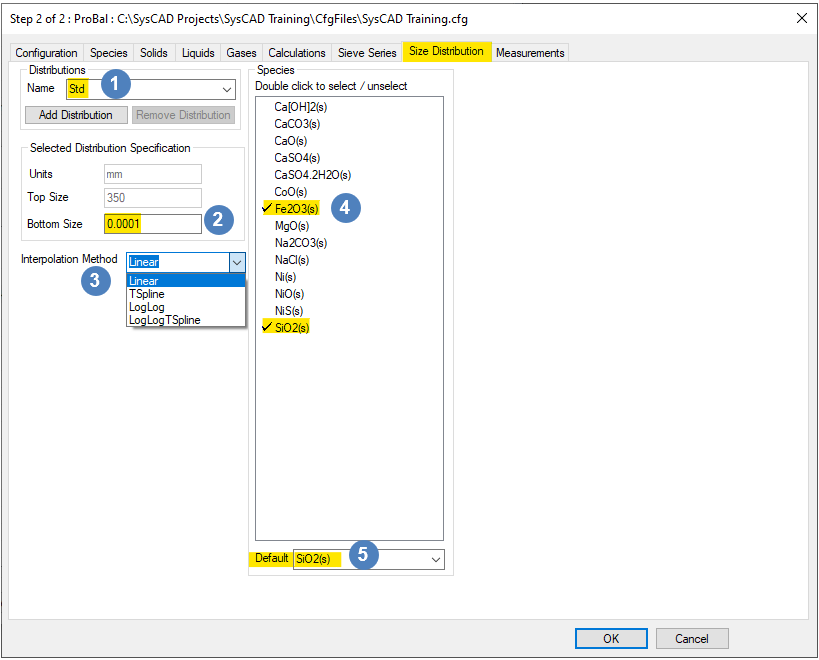
Each Size Distribution has its own sieve series. If a new size distribution is added, the Sieve Series Tab should be used to configure the size data.
| Distributions |
Name | If more than one Size Distribution is available, click on this list box to choose the correct size distribution for Distribution Specification. |
| Add Distribution Button | Adds a new distribution with a default name.
| |
| Remove Distribution Button | Removes a distribution from the list. This is greyed out if there is only one distribution. | |
| Selected Distribution Specification |
Units | This value is displayed only, you may not change it here. It was defined when the Sieve Series was set up previously. |
| Top Size | This value is displayed only, you may not change it here. It was defined when the Sieve Series was set up previously. | |
| Bottom Size | You may define the bottom size for the size distribution, which is used as the lower value for the smallest size interval. This bottom size will be used in some model calculations, in particular it used in calculating the geometric mean of the smallest size interval. NOTE: the bottom size must be less than the Minimum value specified on the Sieve Series tab for the distribution. If the Minimum is set to a value equal to or lower than the Bottom Size, then the Bottom Size will be adjusted to half of the Minimum. | |
| Interpolation Method |
Linear | Linear interpolation is used when performing size distribution calculations. |
| TSpline | TSpline interpolation is used when performing size distribution calculations. A spline is a special function defined piecewise by polynomials. | |
| LogLog | Linear interpolation of the natural logarithm of the size distribution values is used when performing size distribution calculations. | |
| LogLogTSpline | TSpline interpolation of the natural logarithm of the size distribution values is used when performing size distribution calculations. | |
| Select Solid Species | Species |
Selects one or more solid species to contain size data.
|
| Default species |
|
