Example 90 Water
Navigation: User Guide ➔ Example Projects ➔ 90 Water Ionic / 91 Water Molecular
Desalination Example
Project Location
This project appears twice in the examples, once with ionic aqueous species and once with molecular aqueous species.
- ..\SysCADXXX\Examples\90 Water Ionic\Desalination Example.spf
- ..\SysCADXXX\Examples\91 Water Molecular\Desalination Example.spf
Features Demonstrated
- Reverse Osmosis (RO) unit model
- General Separator unit model
- Pressure Exchanger unit model
- General Controller
- Material Flow Section - Water Quality
Brief Project Description
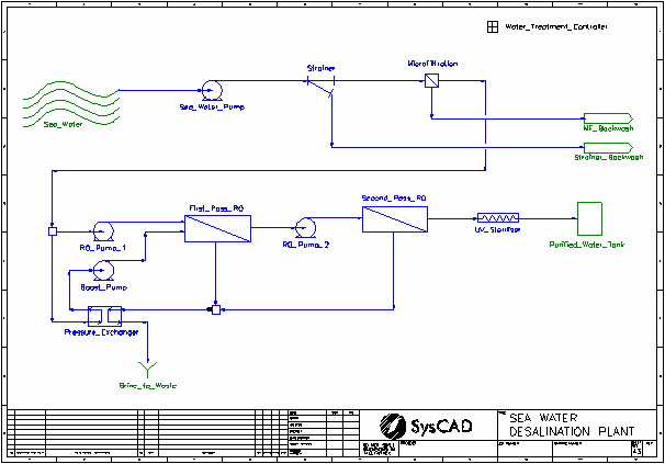
- Seawater is pumped from the sea, through strainer and microfiltration units, both modelled by General Separator unit models.
- The pretreated water is pumped through two Reverse Osmosis (RO) units in series.
- The water product is passed through a UV Steriliser unit, modelled by a Tie unit.
- The brine streams are combined and passed through a Pressure Exchanger to recover energy to a portion of the RO feed stream.
- Pumps are modelled by Tie units. They change the pressure of the stream.
Project Configuration
Most of the configuration of the model is set by the Water Treatment Controller General Controller. The parameters on the four tabs of the controller are described below:
- Overall tab
- The user specifies the sea water feed rate
- The controller calculates the overall yield and efficiency of the circuit.
- Filtration tab
- The user specifies the recoveries of large and small solids in the strainer, as well as the pressure drop and backwash solids fraction.
- The user specifies the recoveries of solids in the microfiltration unit, as well as the pressure drop and backwash solids fraction.
- RO tab
- The user specifies the yield, product impurity fraction, product stream outlet pressure and brine pressure drop for each RO unit.
- The controller calculates the overall RO yield and efficiency.
- The user specifies the efficiency, leakage and high pressure stream outlet pressure.
- Pump tab
- The user specifies the outlet pressures for the sea water and RO pumps.
- Others
- The seawater feed has a typical seawater composition with a salinity of around 36 g/L.
- Both General Separators are configured to use the Solid Separation Split Method. The strainer uses the Bypass to Overflow method to allow a different solid recovery to be used for the small solids.
- Both RO units uses the Impurity Frac efficiency method.
- The Water Treatment controller sets the RO Feed split to the Pressure Exchanger so that the flow matches the Brine feed to the Pressure Exchanger.
- The Pressure Exchanger uses the Set Efficiency method. The unit determines the outlet pressure of the RO Feed stream. The Boost Pump increases the pressure to the same as RO Pump 1.
- The Pressure Exchanger allows leakage of the brine stream (high pressure) into the RO Feed stream (low pressure).
Included Excel Report
Desalination Example Report.xlsx (Available from Build 139.)
This file has the following reports:
- Criteria
- Streams
- Mass Balance
Water Treatment Example
Project Location
This project appears twice in the examples, once with ionic aqueous species and once with molecular aqueous species.
- ..\SysCADXXX\Examples\90 Water Ionic\Water Treatment Example.spf
- ..\SysCADXXX\Examples\91 Water Molecular\Water Treatment Example.spf
Features Demonstrated
- The use of the General Separator unit model
- The use of Makeup Sources and Makeup Blocks
- The use of Reaction Blocks and Reaction Source/Recycle
- The use of PID controllers
- Material Flow Section - Water Quality
Brief Project Description
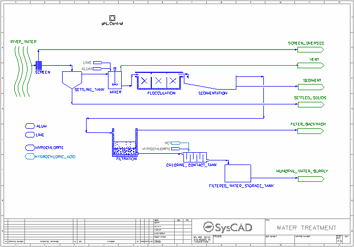
- River water is passed over a screen and through a settling tank, both modelled by General Separator unit models.
- The pretreated water is sent to a mixer Tank, where Alum is added as a coagulant and Lime is added for pH control, both via Makeup Blocks.
- The lime addition is controlled by a PID Controller.
- Precipitation and Neutralisation Reactions take place in the mixer. Gases generated are vented.
- The water passes through a flocculation Tank before solids are separated in Sedimentation and Filtration units, both modelled by General Separator unit models.
- The water product is passed through a Chlorine Contact Tank, where Sodium Hypochlorite is added via a Makeup Block.
- Reactions occur in the Chlorine Contact Tank for the formation of Hypochlorous Acid (HClO) and its reaction with Humic Acid (assumed composition) to form simpler organic species.
- The pipe downstream of the Chlorine Contact Tank has a makeup to allow for pH correction with Hydrochloric Acid if required. This addition is via a Makeup Block and is controlled by either:
- the makeup block itself (ionic version)
- via a PID Controller (molecular version)
- The final product is sent to a Storage Tank and then the municipal supply.
Project Configuration
- River Water Feeder
- The flow is specified as a volume flow.
- Composition is loosely based on typical upland catchment as described in "Principles of Water Quality Control", T.H.Y. Tebbutt, 1992.
- General Separators
- The Screen, Settling Tank, Sedimentation and Filtration units are modelled by General Separator unit models.
- The SolidSeparation Split Method is used with the user specifying the Overflow solids concentration/fraction and the Underflow solids fraction.
- Mixer
- Alum makeup is controlled by mass ratio of Aluminium in alum to total feed flow.
- Lime makeup is a fixed makeup which is set by the pH control PID to pH of 6.
- Reactions include precipitation of Aluminium Hydroxide (Al[OH]3(s)), neutralisation of bicarbonate and reaction of lime (hydroxide) with any leftover acid.
- The Gas Vent split flow operation is used to send all the gases generated to a vent.
- Chlorine Contact Tank
- Hypochlorite makeup is controlled by mass ratio of Chlorine in hypochlorite to total feed flow.
- Reactions include formation of Hypochlorous Acid (HClO) from Hypochlorite and reaction of the acid with Humic Acid into simpler organic species (carboxylic acids).
- The first reaction requires acid, while the second reaction generates acid. The Reaction Source Recycle feature is used allow the acid generated by the second reaction to be used by the first reaction.
- Pipe P_012 (downstream of Chlorine Contact Tank)
- Hydrochloric Acid makeup is a fixed makeup which is controlled by either:
- the makeup block itself to a product molar concentration@25 for H+ (ionic version)
- via the pH control PID to pH of 7 (molecular version)

