Counter Current Decantation (CCD)
Navigation: Models ➔ Mass Separation Models ➔ Counter Current Decantation (CCD)
General Description
The Counter Current Decantation (CCD) model is used in ProBal mode to quickly determine the concentration in the final over and under flow streams from a series of thickeners. The user is required to specify the number of stages in the system. The underflow from the model will have the same percentage solids as the feed to the system. Any solids in the wash stream will report to the overflow stream.
This model is designed to be used as a quick means of determining the effect of differing numbers of stages or wash water ratio in a CCD circuit. The user may also use a number of Counter Current Washer models in series to model a CCD circuit. By using individual Washer models the user can specify mixing efficiencies, which is not available with this model.
Diagram
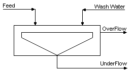
The diagram shows the default drawing of the CCD model, with all of the streams that must be connected to the unit. The physical location of the streams connecting to the model is unimportant. The user may connect the streams to any position on the unit.
Inputs and Outputs
| Label | Required Optional |
Input Output |
Number of Connections | Description | |
| Min | Max | ||||
| Feed | 1 Required | In | 1 | 20 | The slurry feed to the CCD |
| Wash Water | 1 Required | In | 1 | 10 | The dilute wash stream |
| Overflow | Required | Out | 1 | 1 | CCD overflow |
| Underflow | Required | Out | 1 | 1 | CCD underflow |
| Vent | Optional | Out | 0 | 1 | Vent stream (Vapour Only) |
Behaviour when Model is OFF
If the user disables the unit, by un-ticking the On tick box, then the following actions occur:
- All streams connected to the 'Feed' inlet will flow out of the 'Underflow' outlet;
- All streams connected to the 'Wash water' inlet will flow straight out of the 'Overflow' outlet;
- No mixing will occur.
So basically, the unit will be 'bypassed' without the user having to change any connections.
Model Theory
The concentration, Cn, in the final thickener in a CCD circuit containing n stages is calculated using the following formula:
[math]\displaystyle{ \mathbf{\mathrm{C_n=\cfrac{C_l-C_w}{1+WR+WR^2+.......+WR^n}}} }[/math]
where n - Number of stages in the CCD circuit
- Cn - Concentration in stage n
- Cl - Concentration in the slurry feed to the CCD circuit
- Cw - Concentration in the wash water
- WR - Wash ratio = wash water flow / slurry liquor flow.
Assumptions
- No material is leached from the solids in the process.
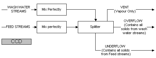
- The efficiency of slurry and wash liquor mixing is 100% in all stages.
- The flowrate of solution from each thickener underflow is equal to the incoming slurry flowrate and the wash water flow equals the thickener overflows.
- There is no allowance for evaporation or the addition of any additional streams.
- All solids from the feed will report to the underflow, all solids from the wash will report to the overflow.
- The outlet temperatures are assumed to be the same as the weighted average of all inputting streams.
References
1. P.M.Page, 'A simple equation for CCD calculations' E/MJ Operating Handbook of Mineral Processing, October 1976.
Flowchart
Data Sections
- CCD_Circuit tab - Contains general information relating to the unit.
- QUF - Available from Build 139. Optional tab, visible if ShowQUF is enabled. This and subsequent tab pages, e.g. QUF.. and Sp, shows the properties of the Underflow stream. The tags in the QUF tab are valid even when the ShowQUF option is not selected.
- QOF - Available from Build 139. Optional tab, visible if ShowQOF is enabled. This and subsequent tab pages, e.g. QOF.. and Sp, shows the properties of the Overflow stream. The tags in the QOF tab are valid even when the ShowQOF option is not selected.
- Info tab - Contains general settings for the unit and allows the user to include documentation about the unit and create Hyperlinks to external documents.
- Links tab, contains a summary table for all the input and output streams.
- Audit tab - Contains summary information required for Mass and Energy balance. See Model Examples for enthalpy calculation Examples.
Counter Current Decantation Page
Unit Type: CCD_Circuit - The first tab page in the access window will have this name.
| Tag (Long/Short) | Input / Calc | Description/Calculated Variables / Options |
| Tag | Display | This name tag may be modified with the change tag option. |
| Condition | Display | OK if no errors/warnings, otherwise lists errors/warnings. |
| ConditionCount | Display | The current number of errors/warnings. If condition is OK, returns 0. |
| GeneralDescription / GenDesc | Display | This is an automatically generated description for the unit. If the user has entered text in the 'EqpDesc' field on the Info tab (see below), this will be displayed here. If this field is blank, then SysCAD will display the UnitType or SubClass. |
Requirements | ||
| On | Tick Box | This allows the user to enable or disable the unit. If the unit is disabled, this is equivalent to bypassing the unit, as the following behaviour will occur:
|
| Stages | Input | The required number of stages, or thickeners, in the CCD circuit. The default is three. |
| OperatingP - NOTE: this pressure is applied to the (combined) feed, before sub-models (if any). | ||
| Method | AutoDetect | If there are any liquids AND no vapours present in the feed, outlet streams will take the highest pressure of the feeds. Else (e.g. some vapours present) outlet streams will take the lowest pressure of the feeds. |
| LowestFeed | Outlet streams will take the lowest pressure of the feeds. | |
| HighestFeed | Outlet streams will take the highest pressure of the feeds. | |
| Atmospheric | Outlet streams will be at Atmospheric Pressure. The atmospheric pressure is calculated by SysCAD based on the user defined elevation (default elevation is at sea level = 101.325 kPa). The elevation can be changed on the Environment tab page of the Plant Model. | |
| RequiredP | Outlet streams will be at the user specified pressure. | |
| IgnoreLowMassFlow / IgnoreLowQm | Tick Box | This option is only visible if the AutoDetect, LowestFeed or HighestFeed methods are chosen. When calculating the outlet pressure and temperature of the tank, SysCAD will ignore the low flow feed streams should this option be selected. The low flow limit is set in the field below. |
| LowMassFlowFrac / LowQmFrac | Input | This field is only visible if the IgnoreLowQm option is selected. This is the amount any stream contributes to the total flow. For example, if the total feed to the tank is 10 kg/s, and this field is set to 1%. Then any feed streams with less than 0.1 kg/s will be ignored in the pressure calculations. |
| PressureReqd / P_Reqd | Input | This field is only visible if the RequiredP method is chosen. This is user specified pressure. |
| Result | Calc | The actual pressure used for the sum of the feeds which will also be the outlet pressure (unless further model options change the pressure). |
| Options | ||
| ShowQUF | Tickbox | Available from Build 139. When selected, the QUF and associated tab pages (e.g. Sp) will become visible, showing the properties of the Underflow stream. See Material Flow Section. Tags in the QUF tab can be used for controllers (e.g.: PGM files) and reports even when this option is not selected. |
| ShowQOF | Tickbox | Available from Build 139. When selected, the QOF and associated tab pages (e.g. Sp) will become visible, showing the properties of the Overflow stream. See Material Flow Section. Tags in the QOF tab can be used for controllers (e.g.: PGM files) and reports even when this option is not selected. |
Results | ||
| WashRatio | Calc | The ratio of Wash Water to the Liquid in the feed stream. |
| SolidWashRatio / SolWashRatio | Calc | The ratio of Wash Water to the Solids in the feed stream. |
Separation Results | ||
| The following table displays the flows and compositions of the Underflow stream. Note: This for slurry only, vapours are excluded. | ||
| UF.MassFlow / UF.Qm | Calc | The total mass flow of the Underflow stream. |
| UF.VolFlow / UF.Qv | Calc | The total volume flow of the Underflow stream. |
| UF.SolidMassFlow / UF.SQm | Calc | The solids mass flow in the Underflow stream. |
| UF.LiquidMassFlow / UF.LQm | Calc | The liquid mass flow in the Underflow stream. |
| UF.SolidFrac / UF.Sf | Calc | The solids mass fraction in the Underflow stream. |
| UF.LiquidFrac / UF.Lf | Calc | The Liquid mass fraction in the Underflow stream. |
| UF.Temperature / UF.T | Calc | Temperature of the Underflow stream. |
| UF.Density / UF.Rho | Calc | The total density of the Underflow stream. |
| UF.SolidConc | Calc | The solid concentration (mass of solids/density of slurry) of the Underflow stream. |
| UF.SolidConc25 | Calc | The solid concentration at 25°C (mass of solids/density of slurry at 25°C) of the Underflow stream. |
| The following table displays the flows and compositions of the Overflow stream. Note: This for slurry only, vapours are excluded. | ||
| OF.MassFlow / OF.Qm | Calc | The total mass flow of the Overflow stream. |
| OF.VolFlow / OF.Qv | Calc | The total volume flow of the Overflow stream. |
| OF.SolidMassFlow / OF.SQm | Calc | The solids mass flow in the Overflow stream. |
| OF.LiquidMassFlow / OF.LQm | Calc | The liquid mass flow in the Overflow stream. |
| OF.SolidFrac / OF.Sf | Calc | The solids mass fraction in the Overflow stream. |
| OF.LiquidFrac / OF.Lf | Calc | The Liquid mass fraction in the Overflow stream. |
| OF.Temperature / OF.T | Calc | Temperature of the Overflow stream. |
| OF.Density / OF.Rho | Calc | The total density of the Overflow stream. |
| OF.SolidConc | Calc | The solid concentration (mass of solids/density of slurry) of the Overflow stream. |
| OF.SolidConc25 | Calc | The solid concentration at 25°C (mass of solids/density of slurry at 25°C) of the Overflow stream. |
| GridDisplay | Tick Box | This is a global selection, if this is selected, then where available, variables will display in a table format, if not selected, they will be listed in separate groups as a single list. |
Adding this Model to a Project
Add to Configuration File
Sort either by DLL or Group:
| DLL: | Separation.dll |
→ | Units/Links | → | Separation: Thickener - Washers(CCD Circuit) | |
| or | Group: | Mass Separation |
→ | Units/Links | → | Separation: Thickener - Washers(CCD Circuit) |
See Model Selection for more information on adding models to the configuration file.
Insert into Project Flowsheet
| Insert Unit | → | Separation | → | Thickener - Washers(CCD Circuit) |
See Insert Unit for general information on inserting units.

