Discussion: Transfer Push and Pull for Batch Processes
Navigation: Product Blog ➔ Discussion Pages ➔ Transfer Push and Pull for Batch Processes
Related Links: Precipitation3, Precipitator3 Dynamic Mode, Dynamic Transfer, Dynamic Transfer Simulation Mode
Overview
The topics of push and pull networks discussed here are broadly applicable to all dynamic processes involving batch operations. So although we discuss this in the context of batch alumina precipitation, any tank-farm operations where each individual tank has multiple inlets and outlets could be modelled with the same techniques.
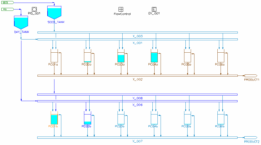
The functionality of the Dynamic Alumina Precipitation model has been extended to allow the precipitator to act as a "network isolator" in a Dynamic model. This simplifies the implementation for complex sequencing models by allowing Transfer Pull operation to control the flows from feed sources. In this example we have a number of rows of tanks which we want to fill, seed, and run for some period of time and then empty sequentially, with the various operations possibly overlapping in time (such that we could have multiple tanks filling or emptying simultaneously). Details of the sequence for an individual tank are described in Batch Mode.
To understand how this new functionality can be used effectively, we will need to start with looking at Dynamic Transfer modes and flow sub-networks.
Transfer Pull vs Transfer Push
A key concept in Dynamic models (compared to steady state models) is the transfer mode in a pipe network and there are two different ways that flow between units can operate - Push and Pull. In Steady State (ProBal) models we are used to just setting the flow in a feeder, and this flow then "propagates" downstream from the feeder - so that whatever we put in comes out the "other end".
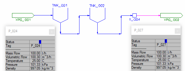
Here we have a simple ProBal flow network of a feeder: two tanks and a tie connected in series. If we introduce a 100 t/h flow at the feeder XPG_001, we will get 100 t/h coming out to the sink XPG_002. In Steady State (and Transfer Push) the flow is effectively controlled at the inlet.
The same model in Dynamic has much more complexity. Dynamic tanks have surge capacity so they can empty and fill, and we are required to specify the volume of the tank (in this case 1000 m3). We are now also able (and generally often required) to control the flow between the tanks. One way this can be done is by setting the capacity in a pipe segment. Dynamic pipes have additional setting compared to ProBal, and there is a Settings tab where we can control the flow, within the FlowCapacity (FC) section. By default, the flow is Unconstrained and CapacityControl is Off:
We can control the capacity by either mass flow or volume flow, so here we change the CapacityControl to ByMassFlow and set the capacity to 50 t/h:
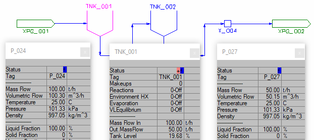
Since we have more flow going into the tank than coming out, the level will rise. Note that the tank will eventually spill unless we add some additional control to either increase the outflow or stop the inflow.
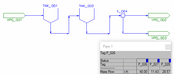
Now let's add capacity limits to both segments of pipe downstream of the second tank TNK_002 (either side of the tie X_004). We set the capacity of the first segment to 40 t/h, and the second segment to 20 t/h.
We now find that 40 t/h is coming out of TNK_002 as specified, but the final pipe segment can only accept 20 t/h, so it starts spilling and indicates a warning. There is actually a FC option on how the model deals with overcapacity, we could change this to Accept which would remove the error.
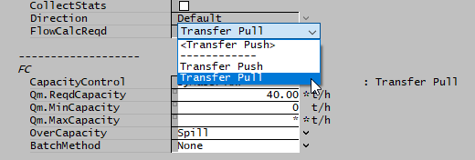
However there is a better way to do this, we can change the last two pipe segments to Transfer Pull using the dropdown list FlowCalcReqd. In Transfer Pull mode, the capacity is now controlled by the minimum capacity in the pipe network downstream of the inlet.
In summary:
- Transfer Push flow is controlled by the capacity at the inlet: whatever you "push" into the system from the source comes out at the end (or via spill).
- Transfer Pull flow is controlled by the least capacity downstream of the inlet: the network will "pull" whatever it needs (or can handle) from the source.
Transfer Pull Demand
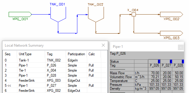
So far this is just part of the picture. If we now add another outlet connected to the tie X_004 and set the required capacity in the pipe to 10 t/h, we find 30 t/h flowing out of TNK_002 with 20 t/h going to XPG_002 and 10 t/h to XPG_003, as expected. However if we set a required capacity of 50 t/h in the new pipe we find that we are not achieving this flow, since we are limited to a maximum flow of 40 t/h in pipe section entering the tie! (Since the pull demand of the two segments of 50+20 t/h cannot be satisfied, SysCAD splits the available flow of 40 t/h between the two in the same ratio as the transfer pull demand.)
To rectify this, we can turn off capacity control in the first pipe segment (allowing unlimited flow) and we can satisfy the requirements in both pipe segments.
This shows that we can add any number of pipe connections to the tie, and control the outflow from TNK_002 by controlling the capacity of each of these pipes individually, with no requirement to set a capacity in the line exiting the tank itself. We can set them all to zero and have no outflow, or have flows in all segments (at least as long as the tank doesn't empty out completely). In ProBal you are probably used to setting the splits in a tie, so that each of the outlets have a specified capacity, but you can't specify the outflows for all of the connections at once; the lowest priority connection just takes whatever is left over once you have specified the others. Using Transfer Pull, you don't need to configure the splits in the tie at all, the tie just transfers the total demand back up the network to the source.
Note here that the so-called "Demand" functionality is specific to the Steady-State solver. In Dynamic models, Transfer Pull is used to achieve this functionality. You may notice that some of the same tags (e.g. QmDemand) are used for propagating data within the transfer pull network.
Push/Pull Local Networks
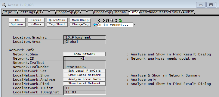
Another important element to understand here is that each Tank model splits the overall network into a number of push or pull Local Networks, and each local network can be controlled independently. You can see the local network with the Local Network button on the Info tab (also indicated by the coloured section of the previous graphic).
The Tanks here act as Network Isolators to allow this partitioning into local networks. In the latest SysCAD release, Build 139.30316, the Precipitation3 unit model now has full network isolator functionality, so completely separates the feed and product networks, allowing these to operate in different Transfer modes, simplifying the control of complex operations such as the batch precipitation example at the beginning of this page.
In a follow-up discussion page we will show how to use PGM classes to work with this new functionality. Each Precipitator is used as the basis of a class model that controls the inflow and outflow from the Precip tank just by controlling the capacity of its inlet and outlet connections.
First Posted: 15 February 2022
Reference Build: 139.30376
For questions or feedback, please contact us at [email protected].
