Batch Mode
Navigation: Models ➔ Alumina Models ➔ Precipitator3 ➔ Batch Mode
| Precipitation3 | Model Theory - Growth | Model Theory - PSD | Model Options | Data Sections | Dynamic Mode | Batch Operations (Probal) |
|---|
Latest SysCAD Version: 25 February 2025 - SysCAD 9.3 Build 139.37016
Related Links: Alumina 3 Bayer Species Model
Introduction
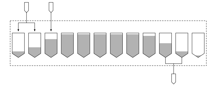
Batch Mode embeds a dynamic model batch process precipitation model into the steady state ProBal implementation. Although the batch process is inherently dynamic in nature, in practice, there are a large number of tanks at various stages in the batch cycle. The (continuous) feed streams are filling one or more tanks, while the (continuous) product stream is being drawn from one or more tanks as well. The final composition of the single product stream is determined by composition of a single batch tank at the end of the dynamic cycle.
The batch precipitator then effectively models the steady state operation of a number of tanks in batch operation, with continuous feed and product streams.
Since the seed stream and pregnant liquor (PGL) streams are introduced at different (and possibly overlapping) times, it is necessary to have separate feeds for these. The basic model then represents the collection of batch tanks as a “black box” with continuous input and output.
Description of Batch Cycle
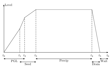
The cycle for a particular tank starts with the tank empty. It is initially filled with PGL, and after some delay, seed is added, which starts precipitation. The PGL and seed filling may overlap. Once the tank is full, it continues to precipitate for a time (determined by the total flow and number and size of tanks), and then drains. After draining, there may be a specified wait time before filling starts again.
Diagramatically, the overall operation for a single tank looks as follows:
During operation, the tank contents may be cooled by a specified heat flow or by heat exchange with an external connected stream. Cooling is enabled and disabled when the tank reaches a specified level during fill and draining.
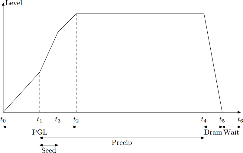
The overlap between PGL and Seed is determined by the parameter SeedOverlap; if this is greater than 1, then seed finishes before PGL:
Setting Up the Precipitator in Batch Operation Mode
New Tabs:
When BatchMode is selected, there are two additional tabs displayed.
- The Batch tab has key parameters and results,
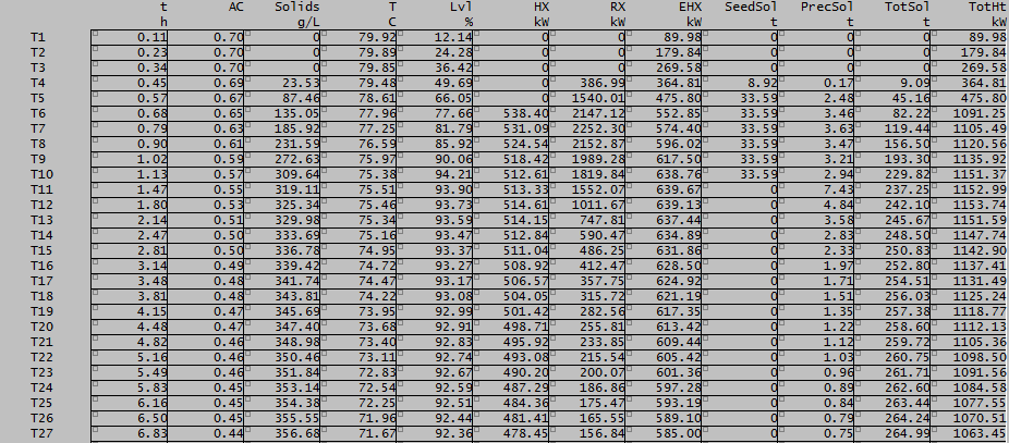
- The Cycle tab shows details of the tank contents at various times during the operating cycle.
Precipitator Options
Most of the standard Precipitator options are available, though these may work differently in Batch Mode.
Please note that the following options are NOT available in Batch mode:
Modes that will work different include
- Evaporation
- Cooling
These will be explained further in the following sections.
Batch Tab
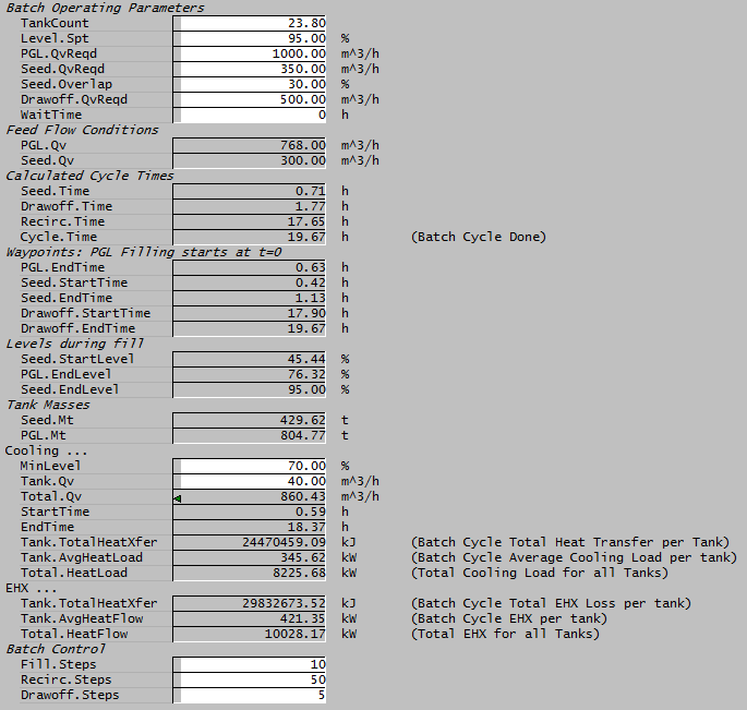
Below is an example screen dump of the Batch Tab, for descriptions of the variables on this tab, please see Data Section - Batch Tab
Cycle Tab
The Cycle tab is divided into 65 time segments, at each time segment, the key results during a batch cycle is shown. For descriptions of the variables on this tab, please see Data Section - Cycle Tab
At the end of the cycle during drawoff , the batch tank contents are effectively pumped into a holding tank though cooling and precipitation continue during the drawoff period. The final composition of the product stream is the composition of the drawoff tank - which represents an "average" composition of the batch tank during the drawoff period (and not necessarily the final composition and temperature of the batch tank at the end of drawoff)
Setting up input Data
- The Seed stream to the batch precipitation tank must contain SSA / Size data. If this is not defined (or in use), the precipitator model will return an error.
- The actual PGL and Seed flow rate need to be defined upstream (e.g. Feeder connected to the Batch Precipitator).
- The PGL and Seed fill rate (on the Batch Tab) can be different to actual PGL and Seed flow rates.
- If they are less, then we are filling multiple tanks simultaneously.
- If they are greater, then we are filling rapidly from a holding tank which is continuously filled from the feed streams.
- If Cooling water streams are connected, the cooling water input is the total cooling water to all Batch precipitators, this value is calculated by the Batch mode, please see Cooling for more information.
Evaporation
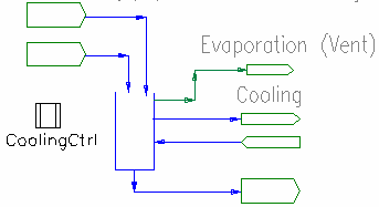
Evaporation is applied to the feed PGL stream only and as the stream is introduced to the tank. Thus evaporative cooling (and consequent mass loss) is already applied when the feed stream is introduced to the tank. If evaporation is present there are two additional parameters on the Precip tab:
- Feed.Evap.T - the PGL feed temperature after evaporation
- Feed.Evap.DeltaT - the temperature drop in the feed stream.
Cooling
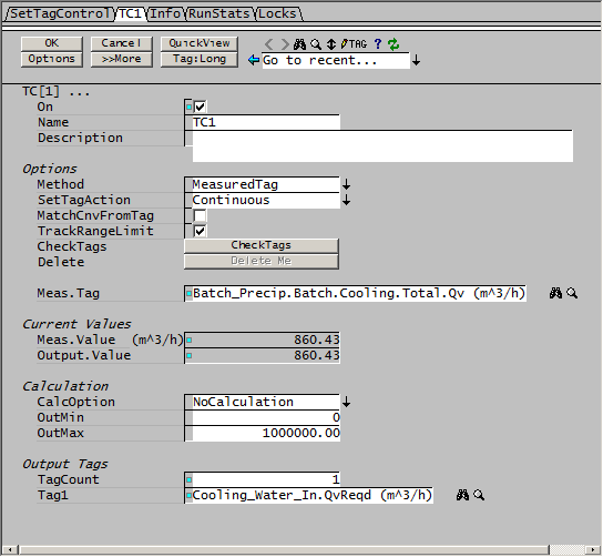
Cooling water flow to an individual tank is specified in the model. However the total flow of cooling water to the batch operation is determined by the batch cycle, since cooling operates only over part of the cycle when the tank reaches a specified level, and this is not determined apriori. The cooling flow is calculated and this value should be transferred to the coolant feed. If the cooling water flow is not correctly set, the predicted temperature rise will be incorrect.
|
The simplest way of doing this is with a SetTag controller
|
|
These issues arise because the batch model is not a true steady state model, it just represents averaged conditions over a dynamic operation.
Additional Technical Information
We have additional technical documentation describing the batch mode operation, contact Kenwalt if you would like to make use of this model.
