Falling Film Evaporation (FFE4) Project
Navigation: User Guide ➔ Example Projects ➔ 10 Alumina: FFE4
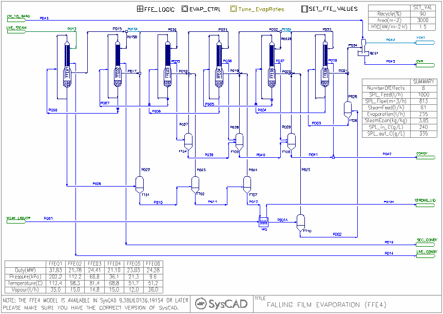
This example project demonstrates the use of a series of Falling Film Evaporators in a flash train arrangement for an Evaporation circuit, rather than the traditional use of a heat exchangers.
Project Location
This is a Steady State project and is stored at:
..\SysCADXXX\Examples\10 Alumina\Falling Film Evaporation (FFE4) Example.spf
Features Demonstrated
- Shows the use of Bayer3 properties model.
- Shows how to set up a multistage Falling Film Evaporator(4) trains.
- Shows how to set up PGM file to set the required model configuration for the circuit.
- Shows how to use the SetTag Controller to change configuration data for multiple units.
- Shows how to set up Annotation Blocks.
Brief Project Description
- The first Evaporator uses live steam, this unit is using All-Demand General CondensingMode for the Condenser Side Operation.
- The remaining evaporators are using the All-Demand Flashtrain CondensingMode for the Condenser Side Operation.
- All Evaporators are using the Flash Train EvapMode for the Evaporator Side Operation.
- Heat transfer coefficient and area are specified for all the evaporators (via the FFE_Logic General Controller).
- Recirculation flows are set up for the evaporators (via the FFE_Logic General Controller).
- The Falling Film Evaporator (FFE4) unit is included in the suite of flashing train models, therefore, SysCAD will auto balance the pressures in this circuit.
- Any ties in the projects will have Split sub model enabled and set to General Operation Mode.
Project Configuration
The configuration of this falling film evaporator has a number of key components:
- Live Steam Addition and Configuration of the first FFE Unit
- In the steam feeder supplying the live steam, please tick the Demand.On option,
- In the FFE01 unit, set the Shell side using the All-Demand General CondensingMode option. This means the unit will estimate the amount of steam required under the Calculated Vapour Flow Demand section (found under the ... tab page), and pass the amount to the feeder (with Demand.On selected).
- The amount of live steam required is set by the FFE heater size, HTC as well as the pressure control within the unit.
- The (Evaporator Pressure) will set flashing conditions for the evaporator, this value needs to be balanced with down stream equipment, that is, the flashed vapour has to be handled by the next stage, it cannot not provide too much. This pressure control is done internally if the FFE unit is connected to other Flash train enabled units. Set the EvapMode to FlashTrain to allow SysCAD to work out the pressure balance.
- Pressure balance and Reflash
- Pressure balance is important in the circuit, each FFE stage needs to have a Pressure control to ensure the flashed vapour + Reflash Vapour can be handled by downstream equipment.
- If the combined vapour is too high, user may need to increase the FFE Heat Transfer Area to accommodate the excess vapour
- It is also important to check the reflash feed points to make sure the reflash vapour is feeding the correct stage.
- The balance of pressure for the reflash stages are done internally by SysCAD in a flash train environment.
- Feed Temperature and Feed Location
- The feed location is important, if the feed is too hot, pre-flash (as shown in the project) may be used, alternatively, feed location may be changed to accommodate the higher temperature.
- Factors affecting heat balance
- Number of FFE stages used - User can turn certain FFE stages off to simulate a circuit with less effects. (Can be done via the FFE_Logic General Controller)
- Extra flashing stages (pre and post), groups of flash tanks can be switched off from the FFE_Logic General Controller.
- Condensate re-flash vapour usage, groups of flash tanks can be switched off from the FFE_Logic General Controller.
- Hot and Cold end Temperature
- FFE configuration, HT Area, HTC, Recirculation, Pressure balance
Running the Project
This example project is set up to be flexible, user may use this project to simulate many different circuit combination:
- Six Effect with flashing - Run the project as is.
- Five Effect with Flashing - in the FFE_LOGIC general controller, set NumberOfEffects to 5, the pgm will turn off FFE02 and its connected flash tank, to simulate a 5 effect circuit.
- Four Effect with Flashing - in the FFE_LOGIC general controller, set NumberOfEffects to 4, the pgm will turn off FFE02 and FFE05, and their connected flash tanks, to simulate a 4 effect circuit.
- Four - Six Effects with NO flashing - in the FFE_LOGIC general controller, turn off PreFlashOn, FlashOn and ReflashOn.
- Four - Six Effects with any flash tank on/off - in the FFE_LOGIC general controller, turn on Manually_Set_Flash, then manually switch on/off any flash tanks in the circuit.
Please note that some combination may not solve.
Debugging the Circuit
Keeping in mind that the circuit is set up to handle a certain range of feed rate, evaporation rate, any dramatic change to the Feed and operating conditions may cause the project to not solve. When this happens, please check the FFE Area, HTC, concentration target etc. are still valid.
Please see Falling Film Evaporator 4 for more information on the model, and Hints and Comments for some general notes.
Tuning model to plant data
User may need to add in pressure drop to the FFE vapour lines when tuning the model to match plant data. The pressure drop values may not be large but they will change the saturation temperature of the flash vapour and reduce the LMTD for the next effect. User may add in the pressure drops manually, or use the Tune_EvapRate controller to try and match plant vapour flowrates.
Heater Sizing
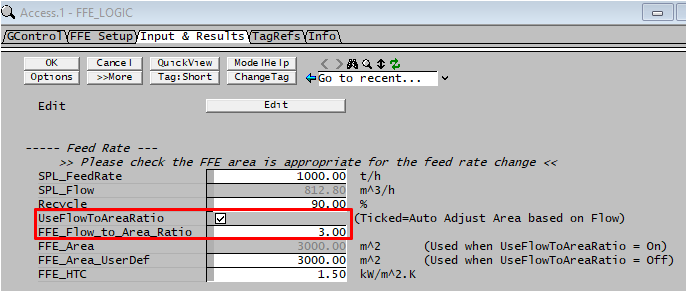
When using this model for different flowrate or operating conditions, users often forget to change the heater size to suit the new flow conditions. Tag included in PGM code to allow the user to "auto" change the heater size based on a flow ratio. This will help with project solve if flow rate used is different to its original value.
User can switch this off to enter user defined data.
Included Excel Reports
- FFEvaporation.XLSX - this excel report show some basic report formats for the project, these include Input Criteria and simple overall balance and Stream data report

