Urea Demonstration Project
Jump to navigation
Jump to search
Navigation: User Guide ➔ Example Projects ➔ 81 Urea
Urea Project
Project Location
This is a Steady State project and is stored at:
..\SysCADXXX\Examples\81 Urea\Demo Urea Project.spf
Features Demonstrated
- Various processes including synthesis, decomposition, hydrolysis, granulation, separation, evaporation, condensation and off gas scrubbing.
- Reactions including Reaction Heat Exchange.
- Heat Exchanger model (Build 138) or Shell and Tube Heat Exchanger 2 (Build 139 or later).
- Gas Pump model.
- User Property Calculations
- Use of General and PID controllers.
- Use of sample Excel report.
Brief Description
- This project simulates a Urea plant. Ammonia (NH3) and carbon dioxide are reacted together to form a urea solution. The urea solution undergoes decomposition and a two-stage evaporation process to produce urea melt. The urea melt is granulated to produce solids urea granulated product. This model is provided as a template, starting data is an estimate only.
Project Configuration
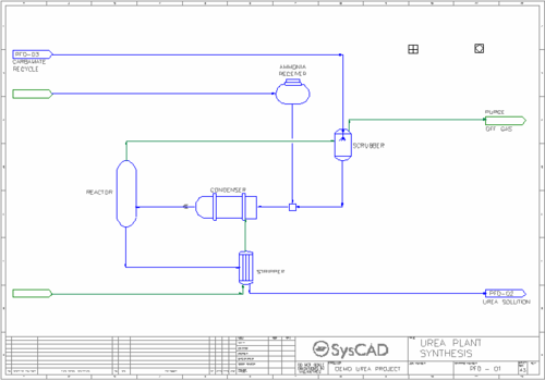
- Synthesis Circuit
- Liquid carbon dioxide is reacted with liquid ammonia in a Reactor to produce liquid Urea and other by-products. The reactions occur at 180 °C and 140 barg pressure.
- A PID controller is used to control the Nitrogen to Carbon ratio in the Reactor outlet by varying the feed rate of the carbon dioxide gas.
- The offgas from the reactor is scrubbed with carbamate recycle solution.
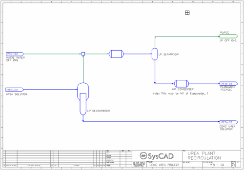
- Recirculation Circuit
- Urea solution from the Synthesis circuit is undergoes decomposition reactions in the Low Pressure (LP) Decomposer. The reactions occur at 180 °C and 4.5 barg pressure.
- Over half of the urea is converted to ammonium carbamate.
- The offgas from the decomposer mixes with the waste water off gas stream and a series of condensation and separation processes produce an offgas stream and a carbamate recycle stream which is returned to the Synthesis circuit.
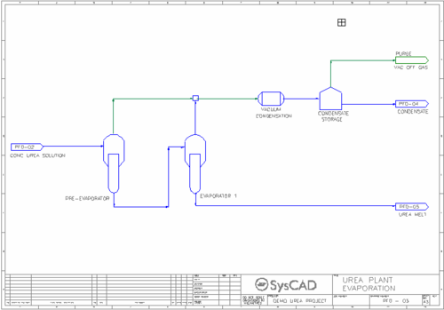
- Evaporation Circuit
- Concentrated urea solution from the Recirculation circuit is passed through a two-stage evaproation process at 135 °C and 0.3 bar pressure (second stage).
- A small fraction of the water evaporates while a small fraction of the urea decomposes to carbon dioxide and ammonia.
- The product from the evaporation process is a urea melt stream.
- The offgas from the evaporators is condensed and after separation of the non-condensables, a condensate stream is produced. The feed to the condensation is under vacuum but the final product is at atmospheric pressure.
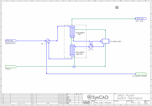
- Water Treatment Circuit
- Condensate from the Evaporation circuit is passed through a series of heat exchangers, scrubbers and a hydrolyser to produce an effluent water stream and an offgas stream.
- Steam is fed to bottom scrubber and hydrolyser.
- Within the hydrolyser, any remaining urea and biuret are decomposed to carbon dioxide and ammonia.
- Granulation Circuit
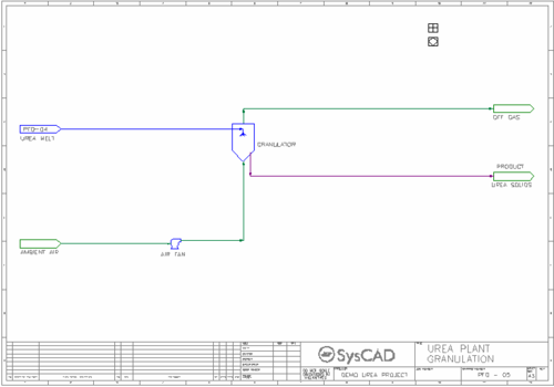
- Urea melt from the Evaporation circuit is sent to a granulator which produces a granulated solid urea product and an offgas stream.
- Ambient air is fed to the granulator after a pressure boost in the Air Fan.
- A PID controller is used to control the final moisture content of the urea product by varying the evaporation of water in the granulator.
- A PID controller is used to control the temperature of the urea product by varying the amount of ambient air fed to the granulator.
- Setting up and Viewing User Property Calculation
- One focus of this example is to show the user how to add in a user property calculation for their project. Once defined, the user property calculation will be available for all the unit operations in the project.
- In Step 2 of Edit Configuration file, add the user property calculation on the Calculations tab.
- One User Property Calculation has been added for NtoC, the elemental ratio of nitrogen to carbon. This will be visible on the Qo/QFeed/QProd tabs on the access window.
Notes:
- Indirect heating and cooling flows are not shown. Instead Reaction Heat Exchange (RHX) functionality is employed.
- Pumps and compressors are not included, pressures are set in vessels.
- Reaction extents are set in Reaction Blocks directly.
- Generally, all reactions occur in the liquid phase. Product gases are evolved afterwards.
Excel Report
- Urea Demo Report shows an example of a report that can be easily setup using the provided default 04DetailedReport.xlsx file.
