Example - 07 ChemApp Projects
Navigation: User Guide ➔ Example Projects ➔ 07 ChemApp
Combustion Example
Project Location
This is a Steady State project and is stored at:
..\SysCADXXX\Examples\07 ChemApp\ChemAppLight\Combustion Example.spf
Available from Build 139.
NOTE:
- This project is mainly for evaluating ChemApp in SysCAD, user must have ChemApp or ChemApp light installed for this project to work. See ChemApp Overview for more information.
Features Demonstrated
- A simple project showing how to incorporate the ChemApp models into a SysCAD flowsheet.
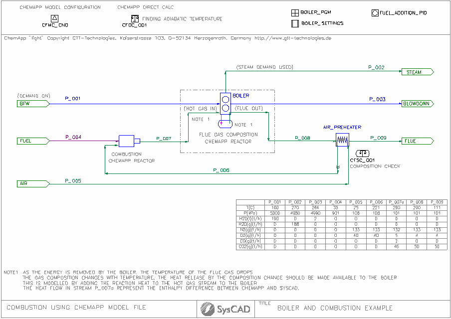
- This project uses the same flowsheet as the Boiler and Combustion Project, for information of the original project, please see Boiler and Combustion Project.
- The project shows the same flowsheet modelled three times, using different unit models to emulate the combustion of fuel and energy transfer to the boiler. These include:
- Flowsheet 1: Using ChemApp reactor for combustion, and for composition of flue gas at the reduced temperature.
- Flowsheet 2: Using FEM reactor for combustion, and for composition of flue gas at the reduced temperature.
- Flowsheet 3: The original flowsheet, using reactions, the flue gas composition is set by user reactions.
- Shows the use of ChemApp Model Configuration.
- Shows the use of ChemApp Direct Calc Model
- Shows the use of ChemApp Side Calc Model
- Shows the use of ChemApp Reactor
Brief Project Description
This project shows how to use simple process units to model complex systems. The Project is set up as two separate sections, Boiler and Combustion.
- Boiler: The boiler section will heat and vapourise the boiler feed water, producing steam at the defined conditions. It will also report the energy required to achieve this.
- Combustion: Fuel is used to produce energy in the combustion chamber, the amount of energy produced is dictated by the boiler.
- Air to the combustion chamber is preheated by heat exchange with the flue gas. Air supply is in excess, done via a general controller.
Project Configuration
- ChemApp Model Configuration:
- A predefined ChemApp Model definition file: CNO.dat is used in this project. This file can be found in the ChemApp installation folder or in this case, the CfgFiles folder.
- The SysCAD species database (SysCAD.93.db3) has been edited to contain the species as defined in the ChemApp model file (CNO.dat). The ChemApp species and SysCAD species are mapped using the IPhaseMap.txt file. The IPhaseMap.txt must exist in the CfgFiles folder.
- Due to the limitation of ChemApp Light, only 30 species can be used by ChemApp SysCAD models.
- The ChemApp model file (CNO.dat) did not include H2O or H2, H2O(g) has set to bypass the ChemApp unit models in this project.
- Also due the species limitation of the CNO.dat model file, the fuel input has changed to C(carb) instead of CH4 used in the original Boiler and Combustion Project example.
- ChemApp direct Calc:
- The ChemApp direct calc model can be set up to check ChemApp calculated values, in this case, a set of "fuel and air" mixture values have been entered to check the adiabatic temperature using ChemApp enthalpy values.
- Note that ChemApp enthalpy may be different to SysCAD enthalpy, as the SysCAD.93.db3 data may not be using the same data as ChemApp.
- Boiler Section:
- User specifies the BFW condition (in the feeder)
- User defines the Final T&P, Blowdown % and boiler efficiency
- SysCAD calculates the heat required for boiling and superheating the steam
- SysCAD calculated the fuel energy requirements based on boiler efficiency. This energy is tells the combustion chamber how much heat is required.
- Fuel Section:
- We have used a dry fuel in this example as H2O is not a ChemApp species in the CNO.dat file.
- The Fuel and air mixture is fed to the ChemApp reactor, using the Enthalpy operation mode. This means the model will keep SysCAD enthalpy values constant, the SysCAD feed Hf@T value should match the SysCAD prod Hf@T.
- The hot mixture is then used to heat and evaporate water in the boiler.
- As the energy is removed by the boiler, the flue gas temperature drops, the air composition will change based on temperature.
- A ChemApp reactor has been added to the flue gas stream to check the gas composition.
- The gas composition should have changed inside the boiler HX section, but since we are trying to emulate this process after the gas has already exited the boiler, we need to transfer the energy back into the boiler feed stream. This is done by adding a EHX on the Hot Gas line.
- A ChemApp side calc model has been added to check the final flue gas composition.
Discussion
Fuel requirement differences:
- User should note that ChemApp and SysCAD uses two different species database, therefore it is possible that the thermodynamic data came from different references. As a result, user will often find mismatch of enthalpy values, this is shown by the different fuel requirements when comparing the ChemApp and FEM case.
- The combustion gas and flue gas composition are not the same, with our simple reaction case, we have assumed the combustion gas composition is the final flue gas composition, thus we have a different fuel prediction in "03 Combustion using reactions" (when compared with the FEM case, while both are using SysCAD enthalpy values).
Nickel Laterite Smelter
Project Location
This is a Steady State project and is stored at:
..\SysCADXXX\Examples\07 ChemApp\ChemAppFull\Nickel_Laterite_Smelter.spf
Available from Build 139.
NOTES:
- This project is mainly for evaluating ChemApp in SysCAD, user must have a Licensed copy of ChemApp installed for this project to work. See ChemApp Overview for more information.
- Example project courtesy of M4 Dynamics Inc, Canada. (www.m4dynamics.com)
- Example cst database is based on published data and collated by M4 Dynamics Inc, Canada. (www.m4dynamics.com)
Features Demonstrated
- A project showing how to incorporate the ChemApp models into a SysCAD flowsheet.
- Shows the use of ChemApp Model Configuration.
- Shows the use of ChemApp Reactor
- Shows the use of advanced features: species suppression, constrained free energy.
Brief Project Description
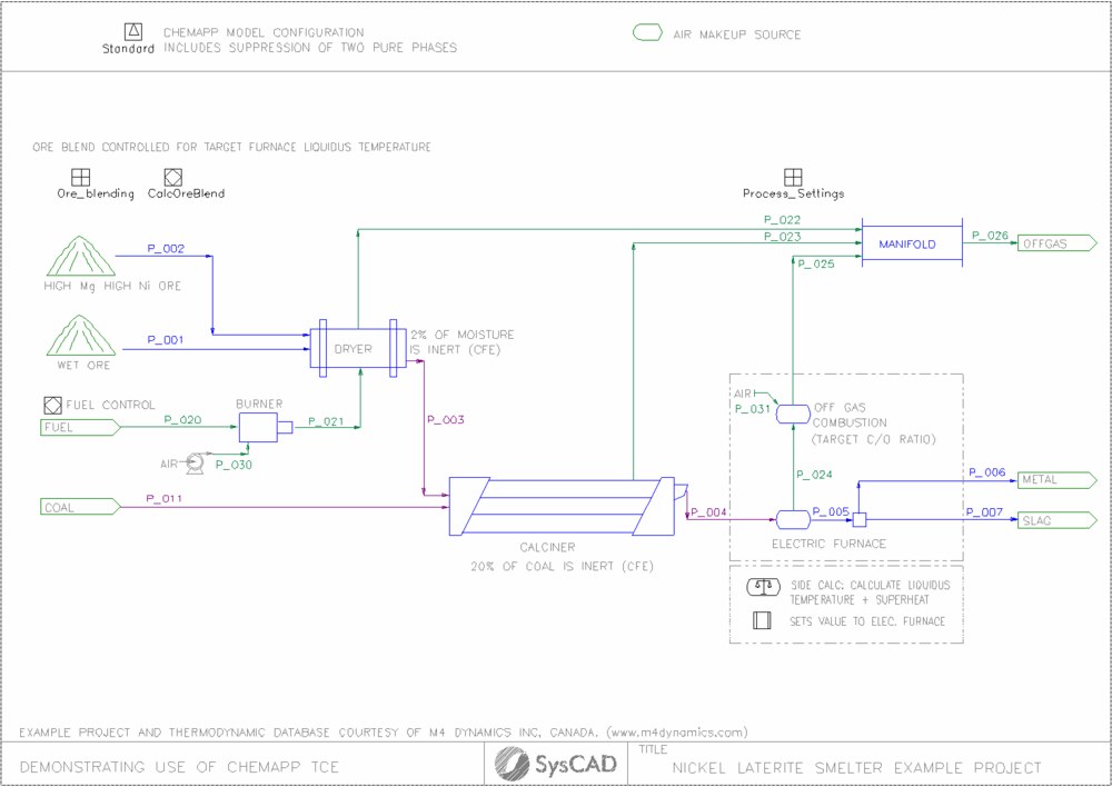
- The objective is to model the Rotary Kiln Electric Furnace (RKEF) process to produce liquid ferronickel at approximately 40% Ni grade, from a serpentine ore containing 2.1%Ni, 22%Fe, 11% crystalline water and a SiO2/MgO ratio of 1.8 (on a mass basis). The initial free moisture content of the ore is 40% by weight.
- The moisture is driven off in the dryer, the dryer energy is provided by burning Fuel (CH4).
- The dried ore then goes through a reduction kiln with addition of Coal. Here, mass transfer and kinetic limitations typically seen in industry limit the amount of coal that reacts and is capable of reducing the ore (Ni and Fe). This effect is simulating using Constrained Free Energy (CFE) method. The kiln also removes the crystalline water contained in the Serpetine ore, converting it partially to olivine and pyroxene.
- The calcine product, partially reduced with residual C, is then sent to an electric furnace where the calcine reduction is finished and melted, to produce crude liquid metal and slag waste.
- Electric furnace offgas is high in CO(g) due to the high temperature and need to be combusted with infiltration air and then combined in a manifold with other process offgas.
Project Configuration
- ChemApp Model Configuration:
- A predefined ChemApp Model definition file: M4D_Laterite_CFE.cst is used in this project. This file was created and supplied by M4 Dynamics Inc, Canada. It can be used by any ChemApp dongle ID.
- The SysCAD species database (SysCAD.93.db3) has been edited to contain the species as defined in the ChemApp model file (M4D_Laterite_CFD.cst). The ChemApp species and SysCAD species are mapped using the IPhaseMap.txt file. The IPhaseMap.txt must exist in the CfgFiles folder.
- User must have a Licensed copy of ChemApp for SysCAD installed, and have the SysCAD TCE license add-on to use this ChemApp model project.
- Some of the phases are suppressed in this configuration. Unselecting these phases will change the simulation results.
- Regarding suppression, some species can only be suppressed if the entire phase is suppressed. In these cases, the suppression of these individual species is deactivated; they can only be suppressed if the entire phase in which they exist is suppressed.
- Ore Feed
- High Mg High Ni ore is blended with the wet ore to achieve a target furnace liquid temperature. The addition of this ore blend has the effect of lowering the silica to magnesia mass ratio, thereby raising the liquidus temperature in the furnace. Blending is accomplished using a PID controller.
- Dryer & Burner:
- The burner is modelled as ChemApp Reactor, using the Enthalpy ChemApp operating mode so that the flame temperature is calculated.
- The Dryer is modelled as ChemApp Reactor, using the Target Temperature Method. The energy required by the dryer will be used to determine the fuel input.
- The products of combustion (burner) is added to the Dryer, where it is mixed with the wet-ore, as water is evaporated the gas is cooled to the specified dryer temperature.
- The fuel input to the burner is controlled using a PID controller. The fuel input is controlled such that the energy required to achieve 105 C operating temperature in the dryer is balanced by the combustion gas addition from the burner.
- Some of the water in the wet ore is "locked" away and does not reach its equilibrium state. This is done by using the constrained free energy (CFE) in the dryer for water. Often this is the case in real laterite dryers, not all the free moisture is removed in the dryers, otherwise, dusting rate increases significantly and equipment utilization is compromised.
- Reduction Kiln:
- The reduction kiln is modelled as ChemApp reactors, using the fixed T mode.
- The amount of Carbon added will influence the degree of calcine metallisation.
- Constrained free energy (CFE) is used for Carbon in the Kiln. This accounts for incomplete utilisation of the coal due to reaction/mass transfer kinetics in the kiln.
- Electric Furnace: this unit is modelled in multiple steps:
- A side calculator added using the Phase Formation mode. The purpose of this side calculator is to calculate the precipitation point of olivine. The point at which olivine just starts to precipitate is the theoretical liquidus temperature. See (Calc_Liquidus)
- The temperature calculated by the side calculator is then set to the electric furnace, with a degree of superheat added. See (TC_001).
- The off gas from the electric furnace contains reduced carbon in the gases. Thus, heat recovery via combustion is simulated by adding air to achieve a target C/O ratio.
- The product stream from the electric furnace is separated into molten liquid metal product and molten slag waste phases. This can be done because each ChemApp phase is matched to a SysCAD individual phase via the IPhaseMap.txt mapping.
Nickel Laterite Smelter Multivariable Optimisation
Project Location
This is a Steady State project and is stored at:
..\SysCADXXX\Examples\07 ChemApp\ChemAppFull\Nickel_Laterite_Smelter(Optimization).spf
Available from Build 139.31866.
This Project requires a Python script to carry out the global optimisation routines using SysCAD COM Automation. The Python scripts is located at:
..\SysCADXXX\Examples\07 ChemApp\ChemAppFull\py_script
NOTES:
- This project requires Python installed in your computer with the following modules: numpy, scipy and pywin32. Follow Python Automation link for instructions to install and setup Python to use it with SysCAD.
- This is mainly for demonstration of global multivariable optimization of a SysCAD + ChemApp Project using SysCAD COM Automation with Python, user must have a Licensed copy of ChemApp installed for this project to work. See ChemApp Overview for more information.
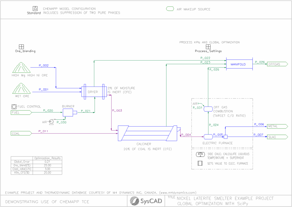
- This Example is based on the Nickel Laterite Smelter example above with slight modifications to introduce a calculation to a Global Error Function that allows an external Python script to optimize several targets simultaneously by manipulating various input parameters.
- Example cst database is based on published data and collated by M4 Dynamics Inc, Canada. (www.m4dynamics.com)
Features Demonstrated
In addition to the features demonstrated in the Nickel Laterite Smelter, this example demonstrates:
- How to setup a Global Error Function to use for multivariable optimisation.
- Shows the use of SysCAD COM Automation and Python Automation.
Brief Project Description
- The objective is to simultaneously achieve target Nickel Grade in crude metal, Slag liquidus Temperature and concentration of FeO in slag
- This is achieved by controlling the fraction of High Ni ore, coal feedrate to kiln and inert fraction of coal in the kiln.
- The latter represents operational conditions that might lead longer or shorter residence time of solids in kiln, resulting in more favorable (or not) conditions for coal to have sufficient time to react in the kiln.
- The PID controller used in the previous model has been removed and the ore blend ratio is to be controlled now externally by the Python script optimiser.
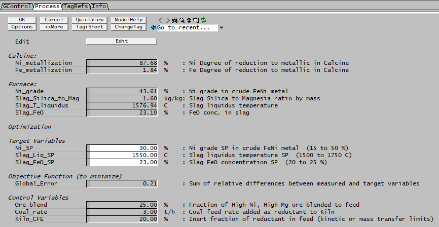
- The Process Settings General Controller has been updated to include calculation of Global Error Function
Project Configuration
- The project is configured in the same way as the Nickel Laterite Smelter example.
- Set points for Nickel Grade, Slag Liquidus Temperature and % of FeO in slag are set in the Process Settings General Controller.
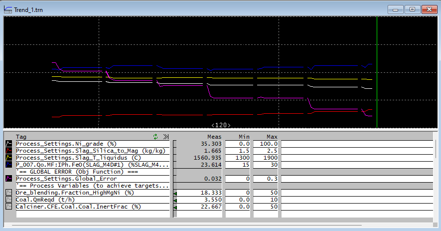
- Trend #1 shows the values of target variables, Global Error and control variables. Use Trend #1 to monitor the progress of the optimisation routine.
Global Error Function Calculation
- The error function [math]\displaystyle{ E }[/math] is defined in the Process Settings General Controller PGM code (see below).
- This function calculates to sum of the squares of the relative differences between the present value and each set point as follows:
- [math]\displaystyle{
E=\left(\frac{Ni_{FeNi}}{Ni_{SP,FeNi}}-1\right)^2+\left(\frac{T_{liq,slag}}{T_{SP,liq,slag}}-1\right)^2+\left(\frac{FeO_{slag}}{FeO_{SP,slag}}-1\right)^2
}[/math]
- [math]\displaystyle{
E=\left(\frac{Ni_{FeNi}}{Ni_{SP,FeNi}}-1\right)^2+\left(\frac{T_{liq,slag}}{T_{SP,liq,slag}}-1\right)^2+\left(\frac{FeO_{slag}}{FeO_{SP,slag}}-1\right)^2
}[/math]
- The tag for the error function Process_Settings.Global_Error is passed to the Python optimiser function to monitor the progress of the routine.
- The PGM code used in this example is shown here:
PageLabel("Process")
TextLabel()
TextLabel("Calcine:")
Real Ni_metallization{@,("Frac","%"),Comment("Ni Degree of reduction to metallic in Calcine")}
Real Fe_metallization{@,("Frac","%"),Comment("Fe Degree of reduction to metallic in Calcine")}

TextLabel()
TextLabel("Furnace:")
Real Ni_grade{@,("Frac","%"),Comment("Ni grade in crude FeNi metal")}
Real Slag_Silica_to_Mag{@,("MRatio", "kg/kg"),Comment("Slag Silica to Magnesia ratio by mass")}
Real Slag_T_liquidus{@,("T","C"),Comment("Slag liquidus temperature")}
Real Slag_FeO{@,("Frac","%"),Comment("FeO conc. in slag")}

Textlabel()
TextLabel("Optimization")
Textlabel()
Textlabel("Target Variables")
Real Ni_SP{i,("Frac","%"),Comment("Ni grade SP in crude FeNi metal")}<15,50><<30>>
Real Slag_Liq_SP{i,("T","C"),Comment("Slag liquidus temperature SP")}<1500,1750><<1550>>
Real Slag_FeO_SP{i,("Frac","%"),Comment("Slag FeO concentration SP")}<20,25><<23>>
Textlabel()
Textlabel("Objective Function (to minimize)")
Real Global_Error@{Comment("Sum of relative differences between measured and target variables")}

Textlabel()
Textlabel("Control Variables")
Real Ore_blend{r,("Frac","%"),Comment("Fraction of High Ni, High Mg ore blended to feed")}
Real Coal_rate{r,("Qm","t/h"),Comment("Coal feed rate added as reductant to Kiln")}
Real Kiln_CFE{r,("Frac","%"),Comment("Inert fraction of reductant in feed (kinetic or mass transfer limits)")}

;--- Logic - executed at EVERY step ---
Ni_metallization = ["P_004.Qo.QM.Ni(FCC_M4D#1) (t/h)"]/["P_004.Qo.QEl.Ni (t/h)"]*100
Fe_metallization = ["P_004.Qo.QM.Fe(FCC_M4D#1) (t/h)"]/["P_004.Qo.QEl.Fe (t/h)"]*100
Ni_grade = ["P_006.Qo.MF.Ni(LiqMetal_M4D) (%)"]
Slag_Silica_to_Mag = ["P_007.Qo.QM.SiO2(SLAG_M4D#1) (t/h)"]/["P_007.Qo.QM.MgO(SLAG_M4D#1) (t/h)"]
Slag_T_liquidus = ["Calc_Liquidus.Prod.T (C)"]
Slag_FeO = ["P_007.Qo.MF.FeO(SLAG_M4D#1) (%)"]

; Calculate Global Error
Global_Error = (Ni_grade/Ni_SP-1)^2 + (Slag_T_liquidus/Slag_Liq_SP - 1)^2 +(Slag_FeO/Slag_FeO_SP -1)^2

Ore_blend = ["Ore_blending.Fraction_HighMgNi (%)"]
Coal_rate = ["Coal.QmReqd (t/h)"]
Kiln_CFE = ["Calciner.CFE.Coal.Coal.InertFrac (%)"]

$ ; --- end of file ---
|
Python script for global optimisation
- Make sure to exit any instance of SysCAD opened before executing this script.
- The script starts by loading the necessary modules (syscadif is included in the python_scripts folder)
- After defining the installation and project folders variables (ScdDir and ScdPrj) a SysCAD COM Interface is defined (sc) and the project is open
- The control variables are defined in the list optTags
- The value to minimise is defined as the Global Error described above in the objTag variable.
- The main routine starts by reading the current values for optTags into a numpy array ystart
- Then the function to optimise f(z) is defined. Here the value of control variables is set in SysCAD, then the model is run and the function returns the error value calculated by the PGM.
- The function to minimise is passed as an argument to the Scipy fmin routine, based in the Nelder-Mead downhill simplex algorithm.
- spo.fmin is an iterative function that will run SysCAD several times while adjusting the values of control variables until the global error value is below a given tolerance threshold.
- Once spo.fmin finds a set of values that minimise the error, the function exists and display the results in the Python prompt.
- The Python script used for this example is shown here
""" ===============================================================
  Script created by KWA Kenwalt
  Global Optimization of Nickel Laterite Example

=============================================================== """
import syscadif

import numpy as np
import scipy.optimize as spo

ScdDir = r'C:\SysCAD139'   ## Installation folder, change if using a different location
ScdPrj = r'\Examples\07 ChemApp\ChemAppFull\Nickel_Laterite_Smelter(Optimization).spf\Project.spj'    ## Saved Project version

sc = syscadif.SysCADCom()
sc.OpenProject(ScdDir+ScdPrj)  ## Open project

optTags =  ["Ore_blending.Fraction_HighMgNi (%)",  "Coal.QmReqd (t/h)", "Calciner.CFE.Coal.Coal.InertFrac (%)"]
objTag = "Process_Settings.Global_Error"

def main():
    ## start from saved solution
    ystart = np.array(sc.getTags(optTags))
    print (ystart)

    def f(z):
        sc.setTags(optTags, z)
        sc.run()
        return sc.getTag(objTag)

    res = spo.fmin(f, ystart, xtol=.1, ftol=.05)
    print (res)

main()
input('Enter to finish')
sc.Close()
|
Results
While the Python routine is executed, the progress of the optimisation can be monitored by displaying the Trend window setup in the SysCAD Project.
- Click on the SysCAD window that opened, and bring up the explorer (Ctrl+E) and select Trend#1
- A live plot showing how the Global Error function approaches zero and the target variables approach the set points
- The Python Output should be something like this (depending on your Python implementation):
SysCADSimulator93.Application
[25.  3. 20.]
Optimization terminated successfully.
         Current function value: 0.000007
         Iterations: 39
         Function evaluations: 73
[15.69642361  3.97749    25.47615711]
Enter to finish
Hybrid GFEM + ChemApp Electric Furnace
Project Location
This is a Steady State project and is stored at:
..\SysCADXXX\Examples\07 ChemApp\ChemAppFull\Hybrid_GFEM_CA_Example.spf
Available from Build 139.
NOTE:
- This project is mainly for evaluating ChemApp in SysCAD, user must have a Licensed copy of ChemApp installed for this project to work. See ChemApp Overview for more information.
- Example cst database is based on published data and collated by M4 Dynamics Inc, Canada. (www.m4dynamics.com)
Features Demonstrated
- A project showing how to build a GFEM non-ideal reactor model of an electric furnace by using a ChemApp side calculation into a SysCAD flowsheet.
- Shows the use of GFEM Reactor and custom settings of activity coefficient of mixture phases
- Shows the use of ChemApp Model Configuration.
- Shows the use of ChemApp Side Calc Model
Brief Project Description
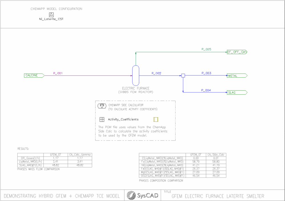
- The model consists of an electric furnace for a Nickel laterite smelter. This is simulated using a Gibbs Free Energy Minimization (GFEM) reactor.
- The feed to the furnace is a typical partially reduced calcine, similar to that produced by a reduction kiln as shown in Nickel Laterite Smelter
- The electric furnace is expected to produce a gas phase (mainly CO), crude liquid metal (ferronickel) and slag. The liquid metal and slag phases are highly non-ideal solutions and excess energy of mixing contributions are necessary to be taken into account to model the distribution of species properly.
- The GFEM reactor allows for custom setting of activity coefficients to incorporate non-ideal or excess Gibbs energy contributions. In this examples, the activity coefficients are calculated at the start of the simulation on a ChemApp sidecalc and transferred to the GFEM reactor.
- The results of the GFEM predictions and ChemApp sidecalc are compared in annotation tables for reference
Project Configuration
- ChemApp Model Configuration (Ni_Laterite_CST):
- The project is configured in the same way as the Nickel Laterite Smelter example.
- GFEM Electric Furnace Reactor (GFEM_EF):
- Calculation mode is set to fixedT
- WithActivity is selected under the Options settings
- ShowQProd is selected to be used for annotation tables display and comparison to ChemApp sidecalc.
- All gas phase components are selected
- Liquid metal components (Fe, Ni and C) are assigned to Phase1
- Slag components (SiO2, FeO and Mg) are assigned to Phase2
- Activity coefficients for the non-ideal phase mixtures (liquid metal and slag) are set by TC_001 set tag controller based on ChemApp sidecalc results
- Reactor temperature is set by PGM
- ChemApp Side Calc (Calc_Gamma):
- Calculation mode is set to Temperature in the TCE OpMode settings
- Calculation is set to Manual in the ChemAppSideCalc tab. This is triggered by the PGM code and only executed once at the beginning of the simulation
- MapToProdStream and show QProd are selected. This is mainly to generate annotation tables to compare results between GFEM reactor and ChemApp SideCalc
- Activity Coefficients (PGM):
- Furnace temperature is set by user at EF_Setting tab
- Activity coefficients for liquid metal and slag components (end-members) are calculated in the pgm code of the Activity_Coefficients general controller.
- Set tag controller:
- A series of set tag controllers are used to set the temperature of the sidecalc to be equal to that of the GFEM reactor and to set the values of activity coefficients calculated in the PGM above into the GFEM reactor settings for the non-ideal phases (liquid metal and slag).
- A series of set tag controllers are used to set the temperature of the sidecalc to be equal to that of the GFEM reactor and to set the values of activity coefficients calculated in the PGM above into the GFEM reactor settings for the non-ideal phases (liquid metal and slag).
Note: The activity coefficients on the GFEM reactor can be set directly from the pgm code on the Activity_Coefficients general controller. This is in fact, the preferred method. However, in this example the set tag controller is use only to demonstrate the use of Tags to set the activity coefficients. Either method produces the same results.
Discussion
- By setting the activity coefficients for non ideal solutions in the GFEM reactor we can capture contributions of excess Gibbs energy of mixing for complex non-ideal solutions.
- The results obtained show a very good agreement between the two calculations engines (GFEM vs ChemApp side calc). However, GFEM is substantially faster in convergence than a ChemApp model, even in this case, where the ChemApp sidecalc is triggered only once instead of at each iteration. For more complex flowsheets, requiring numerous iterations, it might not be possible to calculate the ChemApp sidecalc just once at the start of the simulation. In these cases, it is possible to select to calculate the sidecalc every N iterations or potentially trigger a calculation through PGM by monitoring the input feed to the sidecalc and excute only once a predefine threshold is surpassed.
- It is important to note that the good agreement achieved in Gibbs Energy minimization between the two models is only possible because the same thermodynamic data for compounds is being used by the SysCAD user database and the ChemApp thermodynamic input file (cst). If this is not the case, the user might expect larger discrepancies between the models.
