Troubleshooting Flash Trains
Navigation: User Guide ➔ Frequently Asked Questions ➔ Flashing / Flash Train Questions ➔ Troubleshooting Flash Trains
Related Links: Flash Train
Flash Train not Converging
A typical digestion circuit-flash train can have a number of interacting models and changes made in one part of the circuit can propagate around on different time scales. Demand, PID controllers and Flash macro models supplying steam to heaters will have delays associated with their response, and all these may interact in unpredictable ways. The most useful approach is to remove the propagation of disturbances around the circuit, for example by fixing the digestion outlet temperature as described below.
Here are some things to try:
Reduce the Heat Transfer or Area
Instabilities are often a consequence of having large heat transfer areas for relatively small unit flows and the solver can't get close to a solution initially. The first thing to check is that the specified heater areas, heat transfer coefficients and flash train feed flows and temperatures are reasonable for the situation - especially if you are building new model or making major changes to an existing model. It is also a good idea to check that the any side streams coming into the flash train have sensible temperatures and flows and that they are coming into the flash train at an appropriate location. This is especially important for large flows (such as sweetening or double digest decant overflow return). Steam export from flash trains can also have an impact on stability and large exports of steam can cause excessive cooling - make sure that the any export flow rates are sensible. After you check all the areas, mass flows and temperatures if you still have problems you can try reducing the heater areas or heat transfer coefficients, this may get the model to converge. Once converged, then bring the areas back up to the original numbers. Reducing the area effectively reduces the feedback in the various flash recycle loops: if the areas are reduced to zero, we can obviously find a solution albeit an uninteresting one. Incrementally increasing the area will allow the solver to find a series of stable solutions.
There are however, situations where the larger area model will not remain stable; it will drift away from a converged solution and start to hunt around. These next techniques are useful in these cases.
External Steam Source Pressure Too Low
If there is an external steam source connected to the shell side of a heater in addition to the flash tank, this can cause problems if the pressure of the steam sources is lower than what the flash pressure should be. SysCAD tries to use the lowest pressure that it sees for the flash pressure and this may be so low that more steam is flashed than can be condensed by the heater which will generate an energy balance error. This can happen with the Shell and Tube 1 heater even if the mass flow in the external line is zero. Any external steam source connection to the shell side of a condensing heater that is part of a flash train must have a pressure that is at least as high or higher than the final flash pressure to avoid problems. If there is an external source which is sometimes zero (and thus may appear to be at atmospheric pressure by default), the best approach is to put a tie in the line between the flash tank and the heater shell and add any external steam into the tie rather than to the shell directly - the operating pressure can then be set to ignore low mass flow streams and the proper flash pressure should be used.
Influence of Controllers
If there are PID controllers setting any of the parameters controlling the flash train, make sure that the gain is not set too high. A controller which is unstable can make the whole flash train unstable. For example, a PID controller which is setting steam flow to a digester to achieve a target temperature at the same time as other controllers are setting reaction extents should have a fairly slow time constant.
Fix Digester Temperature
Often in flash train modelling one of the controlled variables is the outlet temperature of the digester.
- The controlled variable is usually live steam flow to the digester itself or an indirect heater before it.
- The outlet from the digester then flashes down through a series of flash tanks which are connected to regenerative heaters.
- The temperature out of the digester affects the amount of heat available to the regenerative heaters and thus the steam requirement to the digester and so this system may be unstable.
One method that can be used is to fix the outlet temperature of the digester to the target temperature using an EHX block and then adjusting the steam flow until actual digester temperature out matches the target.
- When the model is converged, the EHX block is not adding or removing energy and thus has no effect on the solution, but the flash train will be much more stable.
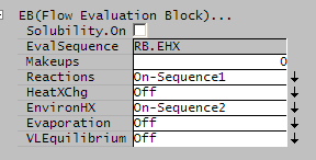
To do this, turn on environmental heat transfer (EHX) in the digester (which is normally a tank unit operation) and make sure that the evaluation order is set so that EHX is evaluated last.
For example:
- if there are reactions, set the sequence to 1 and
- set the EHX sequence to 2 and then
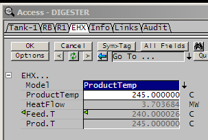
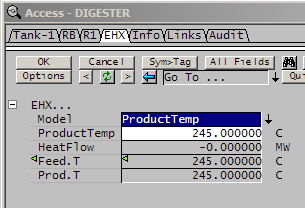
- set the EHX to operate in the product temperature mode and set the outlet temperature to be the target temperature for the digester.
- The steam flow controller should pick up the feed temperature in the EHX block (NB this is the feed temperature to the EHX block after all the chemical reactions have occurred).
This is shown in the screen shots below:
 |
 |
 |
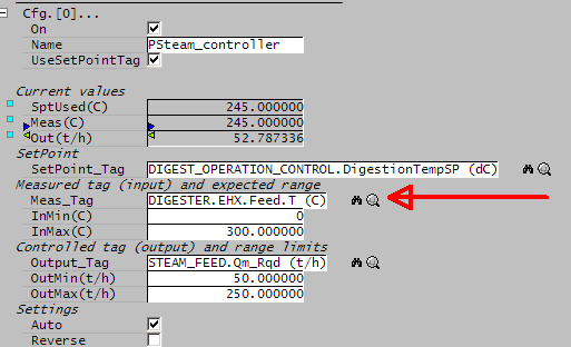
|
Note that there are two screenshots for the EHX block
- one before it has converged showing a temperature in that is different than the target and a significant amount of heat transfer and
- one after it has converged showing that feed temperature in is the same as the target temperature and that there is no heat transfer - i.e. the EHX block has no effect on the solution.
- NB make sure the temperature set point in the controller AND in the EHX block are the same. (recommend using a PGM file or a SetTag Controller to set the same value into the PID controller and the EHX block)
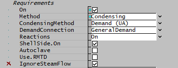
Use "IgnoreSteamFlow" option for condensers with demand
When a condenser is in general demand mode, the demand is determined by calculating the theoretical duty from the steam saturation temperature and LMTD. This may not match the actual steam flow, since the demand flow was set during the previous iteration.
If the steam flow is greater than that needed to supply the theoretical duty, then the excess vapor is vented (if there is a vent connection) or sent out with the condensate. In this case the actual duty is equal to the theoretical duty, and the demand is adjusted so that at the next step the vapor flow is reduced so that no venting should be needed. If, however the steam flow is less than the theoretical duty, the model attempts to fix up by reducing the liquor outlet temperature to account for the shortfall. At the same time the demand is increased - so that at the next iteration the steam supply will be higher.
Under some circumstances this can lead to instability, if there is a PID controller in the digestion circuit also adjusting temperatures, for example by controlling steam flow to an autoclave. The slightly cooler liquor will propagate a drop in temperature around the circuit, which will increase the condenser duty at the next iteration. The demand flow has increased, but the PID controller has also acted to increase the liquor temperature.
The net result is that the condenser goes between insufficient demand and excess demand and the flash train fails to converge. The recommended fix is to avoid using PID controllers for adjusting steam flow to control temperature; instead, as described in the previous section, set the required temperature via EHX to a fixed temperature and adjust the steam flow so that the duty in the EHX block is zero.
As an alternative, there is a (initially hidden) option IgnoreSteamFlow that is by default Off. When enabled, the condenser model does not attempt to fix up the liquor outlet temperature; it just supplies the theoretical duty. This will generally result in energy imbalance while the model is converging, but the demand calculation will ultimately correct the steam flow to match the theoretical duty and any imbalance will disappear once the full model is solved.
- Note that this option should never be used in a standalone condenser - only if the condenser is part of a larger model such as a flash train that will require a number of iterations to converge during which the demand will be adjusted to ensure energy balance.
Make sure you are using an appropriate solution method
SysCAD has two different solution methods that it can use in Steady State mode (Direct Substitution and Adaptive Direct Substitution).
- The default is Adaptive Direct Substitution.
- This method is the most stable for flash train systems.
You can check or change the solver method by opening Solver Setup on the Project Menu and looking on the convergence tab in the pop-up window. The method is shown on the right hand side and can be changed with the drop down menu. For more information on solution methods see Convergence Methods.
Manually Configure Tear Stream Locations
SysCAD designates some pipe in a model to be tear streams as part of the solution method. SysCAD does this automatically and generally does a very good job of it so that the user is usually not required to change which streams are designated as tears. However, with complex flash trains - especially those with multiple parallel heater trains, multiple condensate flash streams, large side streams in or out, significant steam export, etc. there can be situations where stability and convergence can be improved by manually adjusting tear locations.
Normally in a simple flash train, SysCAD places the tears between the heaters. This is the best location because it helps to separate the flash train macro models (flash tanks, vapour lines and heaters) and effectively adds damping in between them. When SysCAD encounters a complex flash train, it may put tears in different locations than between the heaters.
Tears can be manually set in a pipe by going to the first tab and changing 'ReqdType' from "NoTear" to "ManualTear" as shown below. The suggested locations for tear streams are in the liquor lines between heaters.
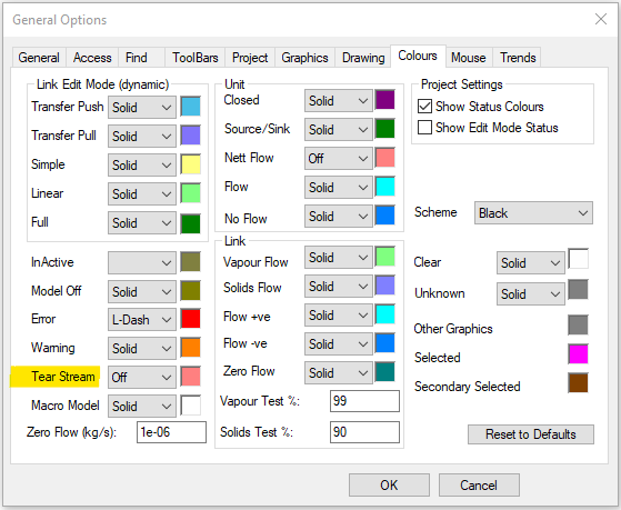
The location of the tears can be seen graphically by setting the colour for tears to be shown. To turn on tear colour go to Menu Tools/General Options, open the colours tab and set tears to show in a different colour from other pipes as shown below;
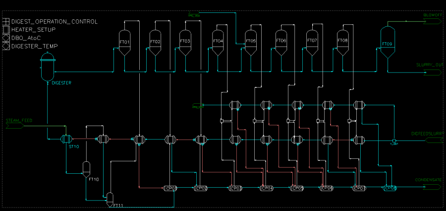
A flash train with highlighted tear streams is shown below;
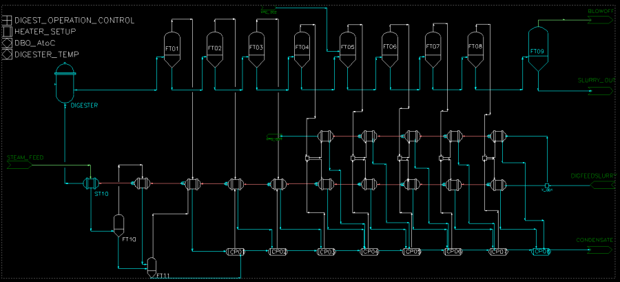
The same flash train with tears relocated is shown below;
Tears in Streams that are part of the Macro Model
Any of the pipes that are part of the macro model must NEVER contain a tear - this will interfere with the solution and SysCAD will not solve. An example of a stream that must not contain a tear is in a stream between a steam source (Flash Tank) and a steam user (Shell and Tube Heat Exchanger). In this case, move the tear to a stream (or streams) that is not part of the macro model.
You should only force enough tears to get the configuration that you require, as adding extra tears will only add numerical overhead. You should also check that tears are in the place that you want them. When you add a tear, generally SysCAD will change another pipe somewhere from a tear to a normal pipe as that tear may become redundant. If that tear was in a place that you wanted it, you may need to manually force it to be a tear.
Reconfigure the flowsheet
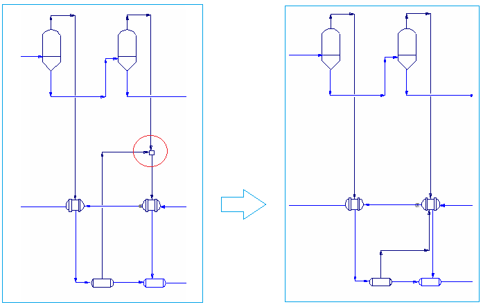
Eliminate ties if that is possible by putting all the flashtank and reflash pot feeds directly into the heat exchanger. In these examples, one converges easily, the other one has problems for large heat transfer areas:
Use damping in the exchanger
The Shell and Tube Heat Exchanger 2 has a damping option. Set all fields to visible, and you will see this option. Experiment with different values of damping. It is possible to have the damping factor less than zero or greater than 1 even.
- If the model is converging, but very slowly and bouncing around, a damping value between zero and 0.5 should be tried to speed up the convergence rate.
- If the model is slowly converging, and seems to be heading towards a stable final result without oscillating about that number, then it is possible to try negative damping, which will accelerate the convergence rate.
- If the model doesn't converge, but bounces around between two values, try a value greater than 0.5
- In drastic cases, try a damping value greater than 1.0.
Use damping on the flash train macro tear
SysCAD has internal damping in its solver. Open the Tear Block access window under View | Solver Setting - Tears.
Under Flash Train Tear Settings section, change the Damp.Min entry, here set to 80%:
Add some global damping
In the View | Solver Setting - GlobalTear access window, there is an option for Global Damping. This can be set to some value based on the guidelines above.
- This approach is likely rather too drastic in most cases, and can slow down overall project convergence.
