Area Model
Navigation: Models ➔ Other General Models ➔ Area Model
This page is for Build 138. The Area Model was removed in Build 139.
General Description
The area model allows groups of models (tanks, feeders, pipes, etc.) to be grouped together and auditing performed on the whole group rather than having to look at the audit pages of each individual model. For example, if Tank01 belongs to Area02, then any spills from Tank01 will be reported in Area02.
A special case of the Area Model is the Global Area, to which all area models belong. The Global Area is the default Area to which new units and links belong.
The main use of the area model is in Dynamic mode:
- All liquid and solid spills will report to the Area model as 'Spill' streams; and
- All gas spills will report to the Area model as 'Vents'.
To assign a model to a specific area, go to the Info Tab on the Access window and select the required area from the Plant Area drop down list. (Please see Plant Area on the Info Tab).
Data Sections
The number of data sections will vary depending if SysCAD is being used in Steady State or Dynamic mode.
- The first section, Area-1, contains general information relating to the material sent to the area.
- The section, Spilt, is only visible in dynamic mode, and contains information relating to material which has been split. This page shows the properties of the sum of the spills sent to the area (see Material Flow Section).
- The section, Vented, is only visible in dynamic mode, and contains information relating to material which has been vented. This page shows the properties of the sum of the vents sent to the area (see Material Flow Section).
- The section, Info, fully described in Info Tab Page Section.
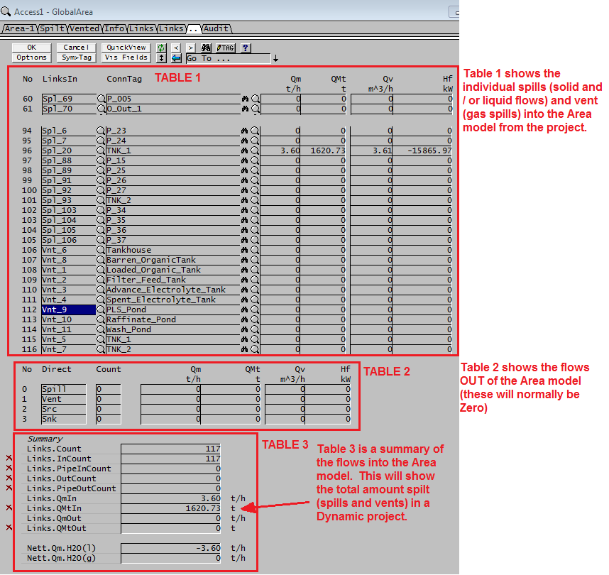
- The section, Links, contains a summary table for all the input and output streams. Please see the Notes below. (The Links Table page contains some information describing the columns.)
- The last section is the Audit. See Model Examples for enthalpy calculation Examples.
Notes for Dynamic Mode:
- The 'Links' tab has 3 tables:
- The first, often quite large, table shows each individual Spill and Vent streams flowing INTO the Area model;
- The second table, with only 4 rows, shows the flows OUT of the Area model. This is NOT the total of the streams shown in the first table.
- The third table, called the Summary IS a summary of the flows into and out of the Area.
- Therefore, if the user wants to see ALL of the spills, including Gas spills (or Vents) then the relevant field will be 'Links.QmIn" for the instantaneous spillage flow, and 'Links.QMtIn' for the total amount spilt over the current run.
Adding this Model to a Project
Add to Configuration File
Sort either by DLL or Group:
| DLL: | Basic1.dll |
→ | Units/Links | → | Process 2: Area | |
| or | Group: | General |
→ | Units/Links | → | Process 2: Area |
See Model Selection for more information on adding models to the configuration file.
Insert into Project Flowsheet
| Insert Unit | → | Process 2 | → | Area |
See Insert Unit for general information on inserting units.
