Barometric Condenser: Difference between revisions
(No difference)
|
Revision as of 08:54, 18 July 2007
Navigation: Models -> Energy Transfer Models
General Description
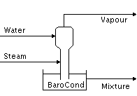
This is a direct contact cooler. The unit has separate water and steam inlets, and mixture and vapour outlets. In most situations the vapour line is connected to a steam ejector.
There are two operational modes, a) as a stand-alone unit or b) as part of a Flash Train. The operational mode is decided by the overall configuration of the flowsheet in which the unit is located. If the Barometric Condenser is correctly connected to other units such as Heat Exchangers and Flash Tanks, the model may become part of the entire Flash Train. The user does not have to specify whether the unit is part of a Flash Train, SysCAD will do this automatically. Refer to Flash Train for the rules governing this behaviour.
If the Barometric Condenser is inserted as part of a Flash Train, see Flash Train for a description of the theory and variables. This documentation will only discuss the variables for a stand alone Barometric Condenser.
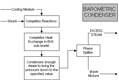
The user may specify reactions, which must occur in the unit. The Barometric Condenser will combine all of the incoming streams to form a homogenous mixture before carrying out the reactions.
An Environmental Heat Loss may also be included in the unit. This allows the user to specify a heat loss, or gain, between the unit and the environment.
The model mixes the inlet streams, rejects heat lost to atmosphere, and performs any reactions, if specified, before flashing the incoming streams. The unit calculates the temperature, composition and flow rate of the exit streams. All of the liquid is pumped from the mixture outlet. The non-condensable vapours and excess steam exit via the vapour outlet at flash pressure.
Diagram
The diagram shows the default drawing of the Barometric Condenser, with the required connecting streams. The vapour connection allows for the removal of non-condensable as well as any excess steam. The user does not have to connect a stream to the vapour outlet.
The physical location of the connections is not important; the user may connect the streams to any position on the drawing. When the user inserts a Barometric Condenser into a flowsheet, he may choose a different drawing from a pull down menu.
Inputs and Outputs
| Label | Input / Output | No. of Connections | Description | |
|---|---|---|---|---|
| Min | Max | |||
| Steam | In | 1 | 1 | The steam inlet. |
| Water | In | 1 | 1 | The liquid or slurry inlet |
| Mixture | Out | 1 | 1 | The outlet, containing the cooling water and condensed steam. |
| Vapour | Out | 1 | Vent for non-condensable and excess steam. | |
Model Theory
The unit is configured to achieve Vapour:Liquid equilibrium at a required pressure using the saturated steam calculations. At this stage, only two phase flash calculations are handled in SysCAD. Any solids that may be in the cooling stream entering the unit are ignored in the flash calculations. However, the enthalpy balance does include the solids. The temperature and amount of material which changes phase is calculated using an adiabatic flash routine1.
The unit will attempt to condense the steam at the user defined flash pressure. If the unit is using the default species model, Standard, then the equilibrium point will be that of saturated steam, as found in Steam Tables.
The equation that is used to calculate the vapour pressure of water is2:
File:Models-Barometric-Condenser-image005.gif
[math]\displaystyle{ \mathbf {\boldsymbol{\rho} = \mathrm{0.1333224*10^\begin{pmatrix}\frac{A}{T}+B*Log_{10}\begin{pmatrix}T\end{pmatrix}+C+T+D\end{pmatrix}}} }[/math]
where
T = Temperature in Kelvin
A = -3433.74
B = -12.0063
C = 0.004782
D = 41.1767
(0.1333224 converts from the pressure from mm Hg to kPa.)
If the unit uses a different species model with an Elevated Boiling point calculation, then the equilibrium point will be adjusted to compensate for the changed boiling point.
References
Coker, A.K., Equilibrium flash calculations quickly computed on PC, Oil & Gas Journal, Jan 14, 1991.
Perry, R.H., Perry's Chemical Engineers' Handbook, McGraw Hill Inc, 6th Edition, 1984.
Flowchart
The following shows the sequence of events if sub model options are switched on. See next heading for more information.
Data Sections
The default sections and variable names are described in detail in the following tables. The default Barometric Condenser access window may consist of 1 section. This number may increase, based on user configuration.
The first section, which has the same name as the Barometric Condenser tag, contains general information relating to the unit, as well as a check box which allows the user to enable the Reaction Block as well as an Environmental heat exchange.
Further sections that may be visible, if the user checks the relevant box on the first page, these are:
- EHX, or Environmental Heat Exchange, fully described in Environmental Heat Exchanger (EHX).
- RB, or Reaction Block, fully described in Reaction Block (RB).
- Audit, fully described in Audit Section. See Model Examples for enthalpy calculation Examples.
First Section -- Tag Name
| Tag / Symbol | Input / Calc | Description |
|---|---|---|
| Requirements: | ||
| Rqd_Flash_Press | Input | The required Flash pressure of the unit |
| Reactions | Tick box | This can be used to switch on the Reaction Block (RB). If this box is checked then the associated page, RB becomes visible and may be configured. Note: The user does not have to configure a reaction file, even if this block is checked. |
| EnvironHX | Tick box | This can be used to switch on Environmental Heat Exchanger (EHX). If this box is checked then the associated page, EHX may become visible and may be configured. Note: The user does not have to configure an environmental heat exchange, even if this block is checked. |
| Results: | ||
| Cond_Press | Calc | The working pressure of the unit |
| Cond_Temp | Calc | The temperature at which the mixture leaves the unit. This will be at, or below, the saturated temperature at the required Flash Pressure. |
| NOTE: EXTRA FIELDS ARE VISIBLE IF BAROMETRIC CONDENSER IS PART OF A FLASH TRAIN. THESE ARE DESCRIBED BELOW. FOR FURTHER INFORMATION PLEASE REFER TO Flash Train. | ||
| Requirements: | ||
| ApproachTemp | Input | The approach temperature of the unit. This number defines the inefficiency of the unit. If the approach temperature is 0°C, then all of the liquid will be used to condense the incoming steam and the final temperature is at the saturation point. If the approach temperature is X, then some of the liquid is not used for condensing the steam and the final temperature is X°C lower than the saturated temperature. |
| Results: | ||
| SuctionP | Calc | The suction pressure. |
| QRqd | Calc | The steam required by the unit. This is determined by the amount of liquid entering the unit and the approach temperature of the unit. |
| Qcond | Calc | The amount of steam condensed in the unit. |
| MinSatPress | Calc | Minimum Saturation Pressure. |
| FlashTrain | Calc | A unique tag assigned to the flash train by SysCAD. Each unit in the flash train will have the same tag in this block. |
| FlashTrainEqp | Calc | This contains a list of all of the equipment tags in this flash train. For example, if this is Barometric Condenser in the above diagram, then the list would be as follows: Baro_Condenser Flash_Tank_3 |
Hints and Comments
<nowiki>a) The unit will flash to the required pressure if there is insufficient cooling water to condense all of the steam. If there is enough cooling water to condense all of the steam and also to cool it, the exiting temperature will be below the saturated temperature.

