Dynamic Plant Example Project
Jump to navigation
Jump to search
Navigation: User Guide ➔ Dynamic Example Projects ➔ Dynamic Plant
Dynamic Plant Example Project
Project Location
This Dynamic Transfer project has three versions and is stored at:
- ..\SysCADXXX\ExamplesDynamic\Dynamic Plant Example.spf
Features Demonstrated
- Reaction files in Dynamic mode
- Use of Profile to add feed at variable rates over time
- Use of Noise to add temperature fluctuation to the feed over time.
- Use of PID controller to control feed rates, and tank levels
- Use of Dynamic Fill to visibly display some parameters on the flowsheet (for example, tank level)
- Shows how to collect Statistic Information
- Shows how to create Excel Trend Reports
Brief Project Description
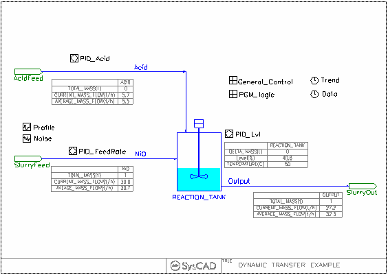
This is a very simple single tank with 2 inputs and 1 output dynamic problem.
- The slurry feed rate to the tank is varied over time using a Feed Profile.
- Acid is added to the tank to maintain a certain concentration on the outlet stream.
- A reaction occurs in the tank.
- The tank outlet rate is varied to maintain a certain tank level.
- All the pipes in this project are set up using the Dynamic transfer mode.
Project Configuration
- RxnTank Set up
- Reactions - There are two ways to define the reactions
- To emulate Reactions occurring in the "mixer box" as it enters the tank, switch on the EB(Flow Evaluation Block) Reactions. Reactions specified here will be the same as per Steady State, where all the mixture will mix and reaction can go to completion instantaneously.
- To emulate Reactions occurring inside the tank, where reaction will occur as a function of time, switch on the CED(Content Evaluation Block) Reactions. Here user can define how fast the reaction will take place (%/s), if the reactants spends enough time in the tank (based on tank size and flow out rate), it may or may not reach completion.
- Tank Inlet / Outlet Connection Heights (Connect Tab)
- Define the Inlet Heights
- Define the Outlet Heights - Outlet Flow will not start until it reaches the outlet height.
- Settings Tab
- Define Tank Height and Volume (Setting Tab), tank level and residence time will be calculated from this information.
- Content.Preset - allows the use of preset and preset Image, as well as preset level and temperature.
- Content.Safety - LowestIOPt, the outlet height (on Connect Tab) may be limited to this minimum safety height.
- PresetImg Tab - Enter information here if preset is to be used.
- Feed Inputs
- Feed flowrate is read from a profile and controlled via controllers.
- Feed Temperature has noise added
- Output Flowrate
- Output is controlled to maintain tank level. Output rate is specified in the output pipe "Output.FC.Qm.Capacity".
- Collect Flow Statistic information
- On the pipe - Settings Tab, Select "CollectStats"
- On the Tank - Settings Tab, Select "Content.DynStats"
- Statistic information will then be collect showing information such as the average, minimum, maximum and total flow.
- Setting up Trends / Trend Report
- Add variables to the Trend Window
- Turn on Historian (recording) for the variable of interest (recorded variables can be used to create Trend Reports)
- Run the project to generate data.
- Set up the Trend Report (See Demo Trends.xls)
Included Excel Report
- Profile1.csv - This is the input file for the Feed
- Demo Report - This file show mass balance and flow statistical information
- Demo Trends - This file shows a trend report format and results.
