Ammonia Projects
Navigation: User Guide ➔ Example Projects ➔ 15 Ammonia
Example 1: Demo Ammonia Project
Project Location
This is a Steady State project and is stored at:
..\SysCADXXX\Examples\15 Ammonia\Demo Ammonia Project.spf
Features Demonstrated
- Shows the use of Compressor
- Shows how to flash/condense NH3 using VLE
- Shows the use of Simple Heaters
- Shows the use of Simple Evaporator
- Shows the use of Simple Condenser
- Shows the use of Simple Heat Exchanger
Brief Project Description
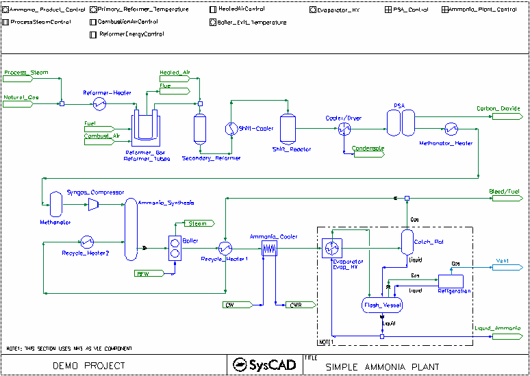
This is a very simplified ammonia plant. It is used to demonstrate how to simulate complex unit operation by using multiple simple unit operations.
For example:
- The reformer is simulated using two Ties unit operations with sub models to handle reactions on both sides as well as heat transfer.
- The Evaporator - Flash Vessel - Catch_Pot operations demonstrate how to flashing/condensing NH3 using VLE. The use of VLE will ensure the partial pressures are correct within the unit operation. (This is much more preferable than using a reaction block with forced extents.)
- Many other unit operations are simulated using Tie/Tank with reaction sub model for component change
- various other heat exchangers are simulated using simple heaters for heat gain/loss.
Project Configuration
- Setting up VLE data for components other than water
- One focus of this example is to show user how to add in flashing/condensing data for their project, to do so, user must first set up the Vapour & Liquid Data in the Species Database:
- Edit the SysCAD.93.db3 file to contain the component requiring flashing/condensing.
- Make sure the component exist in both (l) and (g) form.
- Make sure the Vapour Properties are fully specified for the Gas component, that is, the Vapour Pressure and Critical data are defined. (As per NH3(g) entry in the example project.)
- In the project, user can switch on the VLE sub model where flashing is required, change the Component to the required component. (In this example, NH3. See Evaporator, Flash_Vessel or Catch_Pot in the project.)
- SysCAD will calculate the VLE based on the pressure in the vessel.
- Setting up evaporator and condenser
- The "Evaporator" is set up as Simple Evaporator, the energy required by the evaporator is "transferred" to the other side using a simple heater "Evap_HX". The evaporator is set up with NH3 as its flashing component.
- The "Cooler/Dryer" is set up as Simple Condenser, it is set up with H2O as its condensing component. The VLE block will work out the correct amount of water vapour in the gas stream based on the vapour pressure.
- Setting up Simple Heat Exchanger
- The Simple Heat Exchanger Model works out the flow conditions (for one side) based on the user defined dT information. See Ammonia_Cooler in the project.
- SimpleHX Tab
- Define the required Ammonia outlet temperature
- Select Other.CalcFlow On
- Calc Tab
- DemandConnection set to General Demand, this will allow SysCAD to work out and set the cooling water flowrate. (The Cooling_Water Feeder must be placed into Demand mode for this to work.)
- Define the required Cooling Water temperature
- Cooling Water Supply Feeder
- The Cooling_Water Feeder in this project will provide water demanded by Ammonia Cooler.
- FeederSink Tab, Select Demand.On, check that Demand.Max will cover the flowrate range for the project. Increase this value if necessary.
- QmReqd will represent the minimum value for the water supply. If this value is higher than downstream requirements, the excess amount is distributed. Recommend using a small number of this field.
- Define the operating condition and composition.
- SysCAD will calculate the feed flowrate and display it in the Results:Flow Conditions Qm field.
Included Excel Report
- Example Plant Criteria Report, used to set data into SysCAD as well as reporting back the actual values from SysCAD.
- Example Reactions Report detailing all the reaction and reaction extents used in the project.
- Example Stream Report
Example 2: Demo ASU WEU HBR Project
Project Location
This is a Steady State project and is stored at:
..\SysCADXXX\Examples\15 Ammonia\Demo ASU WEU HBR Project.spf
Features Demonstrated
- Shows the use of Compressor
- Shows how to flash/condense NH3 using VLE
- Shows the use of Simple Heaters
- Shows the use of Simple Condenser
- Shows the use of Simple Heat Exchanger
Brief Project Description
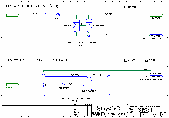
This project can be used to calculate the mass and heat balance of the following system: Production of NH3 (10 mtpd) by means of:
- Splitting Air into Oxygen and Nitrogen using an Air Separation Unit (ASU)
- Splitting Water into Oxygen and Hydrogen Using a Water Electrolyser Unit (WEU)
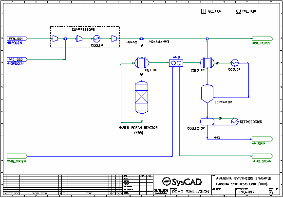
- Reacting the Hydrogen and Nitrogen in a standard Haber-Bosch Reactor (HBR)
Project Configuration
- ASU
- Air consists only of O2 (21 vol%) and N2 (79 vol%) at 1 bar (absolute) and 20 dC
- The ASU consists of one unit and uses Pressure Swing Adsorption technology (PSA)
- The ASU produces 100% pure N2 at 6 bar (gauge) and 40 dC
- General Controller "GC_ASU" is used to set up the ASU.
- WEU
- The WEU consist of one unit and uses Proton Exchange Membrane technology (PEM)
- The WEU produces 100% pure H2 at 20 bar (gauge) and 60 dC
- General Controller "GC_WEU" is used to set up the WEU.
- HBR
- The HBR consists of a compressor, a reactor, an NH3 separator (cooler) and a heater
- Any unreacted H2 and/or N2 is heated and recycled back to the compressor inlet
- The pressure in the reactor is 300 bar (gauge) and the temperature 450 dC
- In the reactor 35% of the hydrogen is converted into NH3
- General Controller "GC_HBR" is used to set up the HBR.
- Setting up VLE data for components other than water
- One focus of this example is to show user how to add in flashing/condensing data for their project, to do so, user must first set up the Vapour & Liquid Data in the Species Database:
- Edit the SysCAD.93.db3 file to contain the component requiring flashing/condensing.
- Make sure the component exist in both (l) and (g) form.
- Make sure the Vapour Properties are fully specified for the Gas component, that is, the Vapour Pressure and Critical data are defined. (As per NH3(g) entry in the example project.)
- In the project, user can switch on the VLE sub model where flashing is required, change the Component to the required component. (In this example, NH3. See HBR_Cooler, Separator or Collector in the project.)
- SysCAD will calculate the VLE based on the pressure in the vessel.
Included Excel Report
- Ammonia HBR Project Report.xlsm
- Example Plant Criteria Report, used to set data into SysCAD as well as reporting back the actual values from SysCAD.
- Example Report for reactions, controllers, and overall mass balance
- Example Stream and flowsheet Report


