Flash Tank: Difference between revisions
| Line 124: | Line 124: | ||
<sub>[[Image:Models-Flash-Tank-image004.gif]]</sub> | <sub>[[Image:Models-Flash-Tank-image004.gif]]</sub> | ||
<math>\mathbf{\mathit{f_1(V_2T_2)=\sum_i \frac {z_i(1-K_i)}{1+V(K_i-1)}=0}}</math> | |||
<sub>[[Image:Models-Flash-Tank-image006.gif]]</sub> | <sub>[[Image:Models-Flash-Tank-image006.gif]]</sub> | ||
<math>\mathbf{\mathit{f_1(V_2T_2)=H^F-V(H^V-H^L)-H^L=0}}</math> | |||
:where: | :where: | ||
Revision as of 03:54, 20 July 2007
Navigation: Main Page -> Models -> Energy Transfer Models
General Description
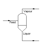
The Flash Tank is used to 'flash' a feed stream to produce a liquid and vapour product at a set pressure. The liquids and vapours leave the unit separately.
There are two operational modes for the flash tank, a) as a stand-alone unit or b) as part of a Flash Train. The operational mode is decided by the overall configuration of the flowsheet in which the Flash Tank is located. For example, if the Flash Tank is connected to other flash tanks, Barometric Condensers and / or heat exchangers, the model will become part of the entire Flash Train. The user does not have to specify that the unit is part of the Flash Train, SysCAD will do this automatically. If the Flash Tank is connected to units other than the previous three, i.e. Feeders, tanks, etc; then the Flash Tank is a stand-alone unit and can be configured as such.
If the Flash Tank is inserted as part of a Flash Train, see Flash Train for a description of the theory and variables. This documentation will only discuss the variables for a 'stand alone' Flash Tank.
Any combination of Vapour Liquid Equilibrium, Environmental Heat Loss or Reaction Block can be configured, if required. Detailed descriptions of these sub-models are supplied separately, but the method of inserting them into the tank, and descriptions of the required variables are given here.
The Vapour Liquid Equilibrium section allows the user to configure which species to flash and / or the flashing method.
Environmental Heat Loss allows the user to specify a heat loss, or gain, between the unit and the environment.
The Reaction Block (RB) allows the user to configure any number of reactions within the flash tank, fully described in Reaction Block (RB).
Diagram
The diagram shows the default drawing of the flash tank, with the required connecting streams. When the user inserts a flash tank into a flowsheet, he may choose a different drawing from a pull down menu.
Inputs and Outputs
|
Label |
Input /Output |
Number of Connections |
Description | |
|
|
|
Min |
Max. |
|
|
Feed |
In |
1 |
20 |
Flash tank feed |
|
Liquor |
Out |
1 |
1 |
Liquor outlet |
|
Vapour |
Out |
1 |
1 |
Vapour outlet |
Model Theory
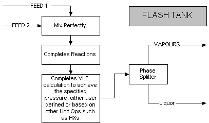
The unit is configured to achieve vapour : liquid equilibrium at a required pressure using the user defined VLE method. At this stage only two phase flash calculations are handled in SysCAD. Any solids that may be in the stream entering the unit are ignored in the flash calculations. However the enthalpy balance does include the solids. The temperature and amount of material which changes phase is calculated using an adiabatic flash routine. The routine used depends on the VLE specified by the user.
The two broad categories of VLE theory used in SysCAD are VLE of a single species or VLE for multiple species using K values1.
Single Component VLE
At this stage only the Temperature : Pressure curves for saturated steam is part of the SysCAD internal data. Therefore, this is the only species that can be used if the single species option is chosen.
The unit will attempt to obtain equilibrium between the vapour and liquor phases of water at the user defined flash pressure. If the unit is using the default species model, Standard, then the equilibrium point will be that of saturated steam, as found in Steam Tables.
The equation that is used to calculate the vapour pressure of water is2:
[math]\displaystyle{ \mathbf {\boldsymbol{\rho} = \mathrm{0.1333224*10^{(\frac{A}{T}+B*Log_{10}(T)+C*T+D}}} }[/math]
where
T = Temperature in Kelvin
A = -3433.74
B = -12.0063
C = 0.004782
D = 41.1767
(0.1333224 converts from the pressure from mm Hg to kPa.)
If the unit uses a different species model with an Elevated Boiling point calculation, then the equilibrium point will be adjusted to compensate for the changed boiling point.
Multiple Component VLE
In this case the model will use K values to determine the phase equilibrium at the required pressure. The K values are either specified by the user, or are the ideal values.
The basic equations that need to be solved to obtain the equilibrium point are:
File:Models-Flash-Tank-image004.gif
[math]\displaystyle{ \mathbf{\mathit{f_1(V_2T_2)=\sum_i \frac {z_i(1-K_i)}{1+V(K_i-1)}=0}} }[/math]
File:Models-Flash-Tank-image006.gif
[math]\displaystyle{ \mathbf{\mathit{f_1(V_2T_2)=H^F-V(H^V-H^L)-H^L=0}} }[/math]
- where:
- V Vapour Flow rate
- T2 Temperature after flash
- zi Mole fraction of component i in the Feed
- Ki Vapour-Liquid equilibrium Ratio of component i.
- HF Enthalpy of Feed
- HV Enthalpy of Vapour fraction
- HL Enthalpy of Liquid fraction
The model will use iterative techniques to solve the above equations simultaneously. If, after a large number of iterations, convergence is not achieved, the model will flag the user with a message that Vapour : Liquid equilibrium was not achieved.
References
Coker, A.K., "Equilibrium flash calculations quickly computed on PC", Oil & Gas Journal, Jan 14, 1991.
Perry, R.H., Perry's Chemical Engineers' Handbook, McGraw Hill Inc, 6th Edition, 1984.
Flowchart
The following shows the sequence of events if sub model options are switched on. See next heading for more information.
Data Sections
The default access window consists of two sections,
a) The first tab has the same name as the model tag, contains general information relating to the unit.
b) Optional tab Reaction Block (RB)
c) Optional tab Vapour Liquid Equilibrium (VLE)
d) Audit, fully described in Audit Section. See Model Examples for enthalpy calculation Examples.
First Section- Tag Name
|
Tag / Symbol |
Input / Calc |
Description |
|
| ||
|
Requirements: | ||
|
OnLine |
Input |
Yes / No - This variable in used to enable flashing in the unit. If the user selects 'No', the material will flow out of the liquor outlet with no change in state; i.e. the unit acts as a pipe. |
|
OtherVapSplit ToLiq (%) |
Input |
This field is to handle any vapour (other than steam) present in the system. User can enter a percentage here to direct the vapour to go out with the steam or with the liquid stream. |
|
PBPress | ||
|
Method |
List |
Atmospheric - flash calculations will be done at Atmospheric Pressure. |
|
Required - flash calculations will be done at the user specified pressure. | ||
|
RequiredT - flash calculations will be done at the user specified temperature. | ||
|
Saturated - flash calculations will be done at the saturated pressure. (This option is only valid if the flash tank is part of a Flash Train configuration.) | ||
|
Reqd |
Input |
The Required Flash Pressure - This is only visible if the Required Method is selected. |
|
ReqdT |
Input |
The Required Flash Temperature - This is only visible if the RequiredT Method is selected. |
|
Result |
Display |
The outlet pressure will be displayed here. |
|
VapSpModel |
Input |
Standard - The default species model. This sets the specie model to be used in the vapour exit stream. This selection has no effect on the model operation. |
|
More options may be available, depending on the user configurations. | ||
|
ShowFeed |
Tick Box |
This will open the QFeed tab pages displaying the combined feed stream information. |
|
TrackVapFd |
Tick Box |
Selecting this will add a warning message and error status colour to the flash tank if vapour is present in the feed stream. |
|
Reactions |
Tick Box |
This can be used to switch on the Reaction Block (RB). If this box is checked then the associated page, RB becomes visible and may be configured. Note: The user does not have to configure a reaction file, even if this block is checked. |
|
VLEquilibrium |
Tick Box |
This MUST be used to switch on Vapour Liquid Equilibrium (VLE). If this box is not checked then the flash tank will operate as a pipe. All feed material will report to the Liquor outlet. When it is checked the associated page, VLE becomes visible and may be configured. |
|
Results | ||
|
Ti |
Calc |
The flash tank feed temperature. |
|
BPEIn |
Calc |
The flash tank feed boiling point elevation. |
|
Flash_Temp |
Calc |
The calculated temperature at the required flash pressure. |
|
Flash_Press |
Calc |
The calculated pressure at the required flash temperature. |
|
QVap |
Calc |
The quantity of flashed vapour. |
|
NOTE: EXTRA FIELDS ARE VISIBLE IF THE FLASH TANK IS PART OF A FLASH TRAIN. THESE ARE DESCRIBED BELOW. FOR FURTHER INFORMATION PLEASE REFER TO Flash Train. | ||
|
PRqd |
Calc |
The required flash pressure calculated by the flash train. |
|
FlashTrain |
Calc |
A unique tag assigned to the flash train by SysCAD. Each unit in the flash train will have the same tag in this block. |
|
FlashTrainEqp |
Calc |
This contains a list of all of the equipment tags in this flash train. For example, if this is Flash Tank 1 in the above diagram, then the list would be as follows: Heat_Exchanger_2 Flash_Tank_1 |
Hints and Comments
- There may be mass entering or leaving the unit via the Reaction Block source or sink, so if the outgoing mass is not the same as the incoming mass, this may be a place to check first.
- If the VLE check box is not ticked the Flash Tank operates as a pipe only. All the material entering the unit leaves in the same state via the Liquor outlet.
- The information in the VLE Section must be correct for the Flash Tank to operate as required. If the VLE configuration requires information that is not available, then the flashing will not occur.

