Example - 04SizeDistribution Projects
Navigation: User Guide ➔ Example Projects ➔ 04 SizeDistribution
Size Distribution Project
Project Location
This is a Steady State project and is stored at:
..\SysCADXXX\Examples\04 SizeDistribution\Size Distribution Example.spf
Features Demonstrated
- How to set up Size Data in the project configuration file, this includes sieve series and solids that contain size distribution data.
- How to switch on the Size Data in the project.
- Size Distribution models Crusher2, Screen 2, Hydrocyclone
- Discontinued Mill-1 and Crusher-1 models have been changed to the Crusher2 model.
Brief Description
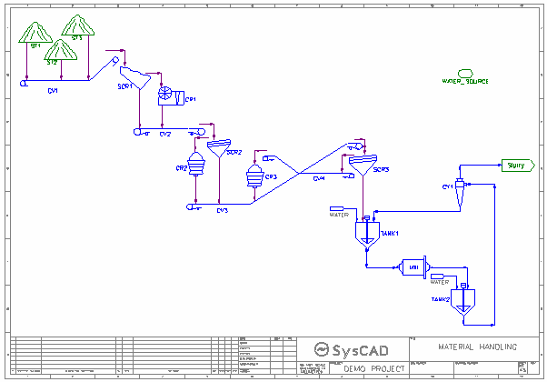
The project shows a very simple material handling project
- Three types of ore (all size data enabled) are added to the project
- The combined ore undergoes a series of processing steps which includes screening, crushing, milling and hydrocyclones.
- Water is added at the Milling and hydrocyclone stages.
Project Configuration
- Setting up and Enabling Size Distribution Data
- The main focus of this example is to show user how to add in size data for their project, to do so, user must first set up the configuration file to include:
- Make sure SizeDst1.dll - Species Qualities - Size Distribution is selected. (Step 1 of Edit Configuration file)
- Select Unit operation that will allow size data, these unit operations may include Crusher2, Screen2, Hydrocyclone, Change Sieve Series and Precipitator(Alumina only). (Step 1 of Edit Configuration file)
- User then needs to set up the Sieve Series, Size Distribution and Measurements Tabs. (Step 2 of Edit Configuration file)
- In the project, user can switch on the size data from the Feeder Content or Pipe Qi Tab. On the unit where size data should start, under the Qualities section, select SzDist.Action to be Create. This will create new Tabs DSz, Sz and MSz.
- Enter the size distribution data in the DSz Tab. If more than one ore with size data is present, then both ore types must have size data entered. (See ST1, ST2 and ST3 in the example)
- Setting up Material Handling Process Units
- The project shows some example setup for Screens, Crushers, Mills and Hydrocyclone.
- PID controllers are used to control the density of streams around the mill.
Included Excel Report
- Material Handling.xls - This file contains
- Feed (Size Distribution Data Set up data for the three feeds)
- Report on Stream data, includes size data.
- Discharge Partition curve and breakage function used for crushers and mills.
- MathandEx.xls - This shows stream data presented on flowsheet.
Milling and Flotation Project
Project Location
This is a Steady State project and is stored at:
..\SysCADXXX\Examples\04 SizeDistribution\Milling and Flotation Example.spf
Features Demonstrated
- How to set up Size Data in the project configuration file, this includes sieve series and solids that contain size distribution data.
- How to setup Flotation units
Brief Project Description
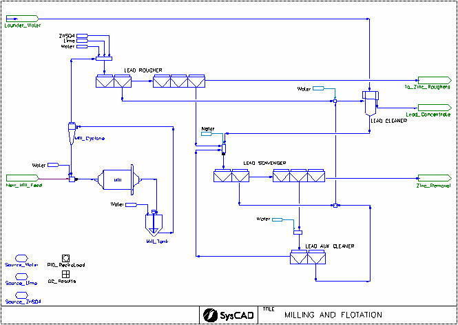
The project demonstrates the use of Flotation units
- Feed is processed through Mill and hydrocyclone prior to the Flotation units. Water is added to control the solids density.
- Multi-stage Flotation cells are used to recover Lead.
Project Configuration
- Setting up and Enabling Size Distribution Data
- See Size Distribution Project for detail.
- Water and Reagent Addition
- Water addition through out the project is done via Makeup Source and MakeUp Block Sub model. Launder Water is added using the Link to MakeupSrc operation type in the Launder Water feeder.
- Reagents are also added prior to the first Flotation Cell.
- Flotation Cell Configuration
- Recovery of Metal can be based on size distribution, shown by Lead Rougher and Lead Scavenger stages. Multiple compounds can contain size distribution data.
- Recovery of Metal can be based on recovery and concentrate grade of a solid species, shown by Lead Auxiliary Cleaner.
- Recovery of Metal can be based on elemental recovery and solids mass pull, shown by Lead Cleaner.
- Recovery (or concentrate grade) of other metals/species can be separately specified, shown by Lead Auxiliary Cleaner.
Included Excel Report
- Milling and Flotation Report.xls - This file include Criteria Report, Size Distribution Data and Stream data.
Milling and Magnetic Separation Project
Project Location
This is a Steady State project and is stored at:
..\SysCADXXX\Examples\04 SizeDistribution\Milling and Magnetic Separation Example.spf
Features Demonstrated
- How to set up Size Data in the project configuration file, this includes sieve series and solids that contain size distribution data.
- How to set up Comminution models.
- How to emulate the magnetic separation using the Solids Recovery Unit.
- How to emulate the thickener using General Separator to allow separation based on size distribution.
Brief Description
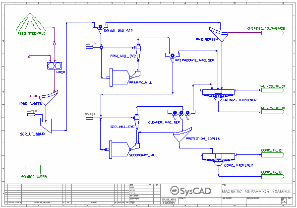
The project demonstrates the use of Solids Recovery Unit model to emulate magnetic separation:
- Feed is processed through Crusher and Screen prior to the Magnetic Separation units (modelled as Solids Recovery Unit). Water is added to control the solids density.
- The magnetite rich stream is the concentrate where recovery is defined.
- The project also demonstrate the use of screen model to emulate the thickener separation, this will allow size data be specified in the overflow and underflow streams.
NOTE: In earlier builds, the Solids Recovery unit was replaced with the Flotation Cell.
Project Configuration
- Setting up and Enabling Size Distribution Data
- See Size Distribution Project for detail.
- Water Addition
- Water addition through out the project is done via Makeup Source and MakeUp Block Sub model.
- Solids Recovery Unit Configuration (or Flotation Cell unit configuration for earlier builds)
- The recovery can be based on overall recovery, multiple compounds can be recovered, Non-mags can be specified with 0% recovery. Shown in the project by INTERMEDIATE_MAG_SEP.
- The recovery can be based on size distribution data, multiple compounds can contain size distribution data. Shown in the project by ROUGH_MAG_SEP and CLEANER_MAG_SEP.
- Mill Configuration
- The size distribution data can be defined as Overall Test Data (PRIMARY_MILL) or Individual Test Data (SECONDARY_MILL).
- The Crusher2 unit model is used to emulate the mill operations.
- Thickener Configuration
- The Thickener model does not allow specification of size distribution, in Steady State Mode, user can use the General Separator model to replace the Thickener model.
- On the Separ tab: Set the SplitMethod to "Solid Separation", SolidsSeparMethod to "Solids PSD", and SolidMethod to "Partition Curve".
- The PartCrv Tab allows the user to specify the percent of feed solids in each size interval reporting to oversize.
- The oversize is the Thickener Underflow.


